Sheet holder positioning apparatus during sensor single crystal silicon etching process

An etching process and positioning device technology, applied in crystal growth, chemical instruments and methods, post-processing details, etc., can solve the problems of offset, affecting the etching effect, uneven contact between single crystal silicon and plasma, etc., to achieve precision Improved, smooth rotation effect

Active Publication Date: 2015-10-14
江苏德尔森控股有限公司
View PDF7 Cites 4 Cited by
  • Summary
  • Abstract
  • Description
  • Claims
  • Application Information

AI Technical Summary

Problems solved by technology

[0002] During the processing of monocrystalline silicon for sensors, it needs to be etched; in the existing etching process, it is often done by stacking multiple monocrystalline silicon Introduce the reactive gas at the position, and make the reactive gas generate plasma in the electric field environment to etch the single crystal silicon; the rack usually needs to be rotated during the etching process to increase the contact uniformity between the single crystal silicon and the plasma However, the rotation of the rack may cause it to shift, resulting in uneven contact between the single crystal silicon and the plasma, thereby affecting its etching effect

Method used


Image

  • Sheet holder positioning apparatus during sensor single crystal silicon etching process
  • Sheet holder positioning apparatus during sensor single crystal silicon etching process

Examples


Embodiment 1

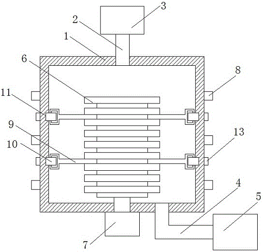
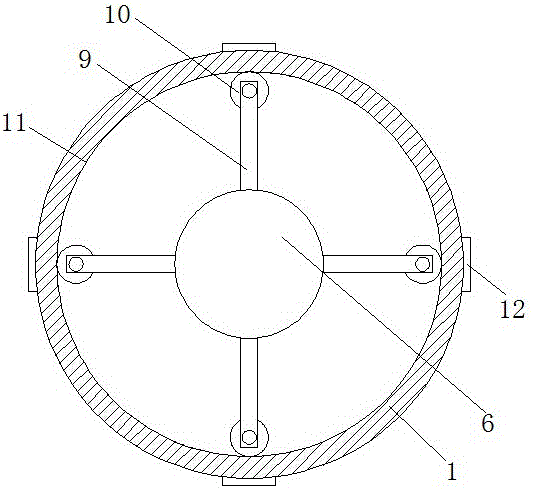
[0019] Such as figure 1 A rack positioning device in the process of etching single crystal silicon for sensors is shown, which includes a reaction chamber 1, and the upper end of the reaction chamber 1 is provided with a gas supply pipe 2, which is connected to a gas source provided outside the reaction chamber 1 Chamber 3, the lower end of the reaction chamber 1 is provided with a suction pipe 4, which is connected to a vacuum pump 5 arranged outside the reaction chamber 1; 1. An external rack rotation mechanism 7, which specifically includes a motor; an electromagnetic coil 8 is arranged outside the reaction chamber 1; in the reaction chamber 1, a plurality of supports extending in the horizontal direction are arranged on the rack 6 Rod 9, the end position of each support rod 9 is provided with a guide wheel 10, which is connected with the support rod 9 through a rotating shaft, the axis of the guide wheel 10 is parallel to the axis of the reaction chamber 1, and the guide w...

Embodiment 2

[0024] As an improvement of the present invention, in the reaction chamber, the corresponding horizontal position of each support rod 9 is provided with a guide rail 11 extending along the side end surface of the reaction chamber 1, and the guide wheel 10 extends to the guide wheel 11 Inside, it can pass through the guide track to make the guiding effect of the guide wheel more accurate, so as to avoid its deviation in the axial direction of the reaction chamber.

[0025] The remaining features and advantages of this embodiment are the same as those of Embodiment 1.

Embodiment 3

[0027] As an improvement of the present invention, a rubber layer is provided on the side end surface of the guide rail 11, which can pass through the rubber layer to absorb the mechanical vibration generated by the guide wheel during operation.

[0028] The remaining features and advantages of this embodiment are the same as those of Embodiment 2.


PUM

PropertyMeasurementUnit
thicknessaaaaaaaaaa

Abstract

The present invention discloses a sheet holder positioning apparatus during a sensor single crystal silicon etching process. The sheet holder positioning apparatus comprises a reaction chamber, wherein the axial line position of the reaction chamber is provided with a sheet holder, the sheet holder is connected to a sheet holder rotating mechanism arranged outside the reaction chamber, the outer side of the reaction chamber is provided with an electromagnetic coil, a plurality of support rod members upward extending in a horizontal direction are arranged on the sheet holder inside the reaction chamber, the end portion positions of each support rod member are respectively provided with a guide wheel, the guide wheels and the support rod members are connected through rotation shafts, the axial line of the guide wheel is parallel to the axial line of the reaction chamber, and the guide wheels intersect on the inner wall of the reaction chamber. With the sheet holder positioning apparatus using the technical scheme, the sheet holder can be subjected to the positioning treatment through the plurality of the support rod members during the sheet holder etching processing process inside the reaction, such that the sheet holder can always be at the axial line position of the reaction chamber so as to improve the etching processing precision of the plurality of the single crystal silicon in the sheet holder.

Description

technical field [0001] The invention relates to a processing device for sensor components, in particular to a chip holder positioning device in the etching process of sensor single crystal silicon. Background technique [0002] During the processing of monocrystalline silicon for sensors, it needs to be etched; in the existing etching process, it is often done by stacking multiple monocrystalline silicon Introduce the reactive gas at the position, and make the reactive gas generate plasma in the electric field environment to etch the single crystal silicon; the rack usually needs to be rotated during the etching process to increase the contact uniformity between the single crystal silicon and the plasma However, the rotation of the rack may cause it to shift, resulting in uneven contact between the single crystal silicon and the plasma, thereby affecting its etching effect. Contents of the invention [0003] The technical problem to be solved by the present invention is t...

Claims


Application Information

Patent Timeline
Patent Type & Authority Applications(China)
IPC IPC(8): C30B33/08
Inventor 牟恒
Owner 江苏德尔森控股有限公司
Why Eureka
Try Eureka