
Digestion device for protein measurement

A digestion apparatus and protein technology, applied in the field of digestion apparatus, can solve the problems of slow temperature rise, large power consumption, internal pressure of digestion tank, etc., and achieve the effect of fast temperature rise and low energy consumption

Active Publication Date: 2015-10-14
QIQIHAR UNIVERSITY
View PDF17 Cites 0 Cited by
  • Summary
  • Abstract
  • Description
  • Claims
  • Application Information

AI Technical Summary

Problems solved by technology

[0003] The purpose of the present invention is to solve the problems of external heating or microwave heating in existing digestion instruments, which have the problems of large power consumption, slow temperature rise, and internal pressure of digestion tanks, and provide a protein determination digestion instrument

Method used


Image

  • Digestion device for protein measurement
  • Digestion device for protein measurement
  • Digestion device for protein measurement

Examples


specific Embodiment approach 1

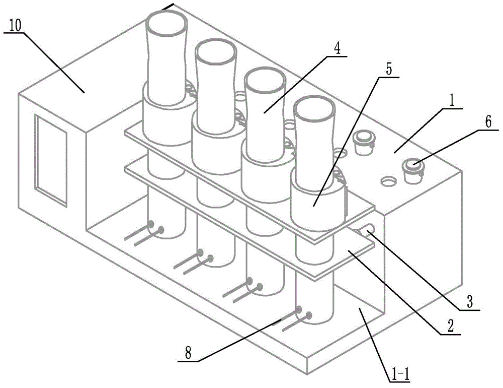
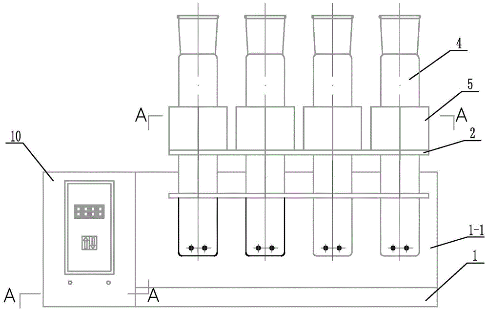
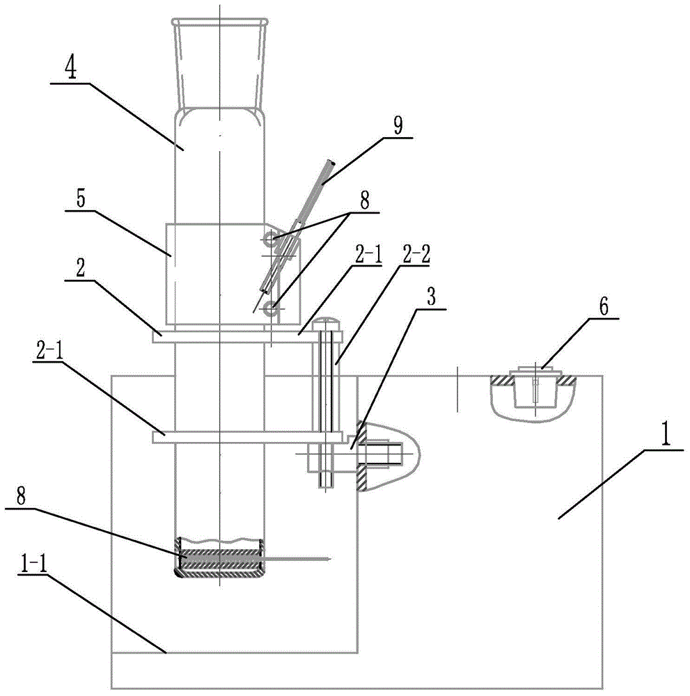
[0020] Specific implementation mode one: combine Figure 1 to Figure 8 Describe this embodiment. This embodiment includes a chassis 1, a mounting seat 2, several horizontal base columns 3, several internal heat digestion tubes 4, several temperature control seats 5, several switches 6, several through pipes 7, several A U-shaped heating wire 8 and several temperature sensors 9,

[0021] The front end of the cabinet 1 is provided with a right-angled groove 1-1 for placing the internally heated internal heat digestion tube 4, one side of the cabinet 1 and the end of the right-angled groove 1-1 is an electrical control box 10, several horizontal base columns 3 It is arranged in parallel in the right-angle groove 1-1 and connected with the chassis 1 through connecting elements. The installation base 2 is arranged on the horizontal base column 3 and connected with the horizontal base column 3 through connecting elements. Several internal heat digestion pipes 4 are vertically and pa...

specific Embodiment approach 2

[0023] Specific implementation mode two: combination Figure 9 ~ Figure 12 To illustrate this embodiment, the center of the temperature control seat 5 of this embodiment is provided with a digestive tube installation hole 5-1 along the vertical direction, and the side wall of the temperature control seat 5 is provided with an inclined hole 5-2 and two straight holes. Hole 5-3, inclined hole 5-1 is inclined from top to bottom and from outside to inside, two straight holes 5-3 are arranged in parallel up and down, and the centerline of straight hole 5-3 and the centerline of digestive tube installation hole 5-1 perpendicular to each other. The digestion tube installation hole 5-1 is used for installing the internal heat digestion tube 4, the oblique hole 5-2 is used for installing the temperature sensor 9, and the straight hole 5-3 is used for installing the U-shaped heating wire 8. Other components and connections are the same as those in the first embodiment.

specific Embodiment approach 3

[0024] Specific implementation mode three: combination Figure 13 Describe this embodiment, one end of the horizontal base column 3 of this embodiment is a cylinder, the other end is a bolt 3-1, the upper end surface of the cylinder is provided with a horizontal plane 3-2, and the cylinder is provided with a horizontal plane 3-2. Vertical connecting holes 3-3. The bolt 3-1 is used to connect with the nut so that the horizontal base column 3 is fixed on the chassis 1, the horizontal plane 3-2 is used to support the mounting base 2, and the connection hole 3-3 is used to install connecting elements so as to fix the mounting base 2 On the horizontal base column 3. The other components and connections are the same as those in the second embodiment.


PUM


Abstract

Disclosed is a digestion device for protein measurement, which relates to a digestion device. A right-angle container is formed in the front end face of a chassis; an electric appliance control box is arranged at one side of the chassis and at an end part of the right-angle container; a plurality of transverse foundation pillars are arranged in the right-angle container in parallel and are connected to the chassis; a mounting base is arranged on and connected to the transverse foundation pillars; a plurality of internal heating digestion pipes are vertically arranged in the mounting base in parallel; a lower part of each internal heating digestion pipe is provided with two transverse holes internal heating digestion pipe perpendicular to axes of the internal heating digestion pipes; each transverse hole is internally provided with a through-tube; each through-tube is internally provided with a U-shaped heating wire; each internal heating digestion pipe is corresponding to a switch and a temperature control base; the temperature control bases are fixedly sleeved in the internal heating digestion pipes; the side wall of each temperature control base is equipped with a temperature sensor and two U-shaped heating wires, wherein the temperature sensor and the U-shaped heating wires are connected to the electric appliance control box via conductive wires; and a plurality of switches are installed on the upper end face of the chassis, and are connected to the control box through conductive wires. The digestion device is used for measuring protein in various biological and plant samples.

Description

technical field [0001] The invention relates to a digestion instrument, which belongs to the field of analytical instrument manufacturing, in particular to a protein determination digestion instrument. Background technique [0002] Known digestion instruments are external heating digestion instruments or microwave digestion instruments. The external heating digestion instrument has a large power consumption and slow temperature rise; the internal pressure of the digestion tank of the microwave digestion instrument should be greater than 200Kg / cm 2 , therefore, there is a security risk. It is necessary to design an internal heating digestion instrument with fast heating, low pressure and low energy consumption. Contents of the invention [0003] The purpose of the present invention is to solve the problems of external heating or microwave heating in the existing digestion apparatus, which have the problems of large power consumption, slow temperature rise, and internal pr...

Claims


Application Information

Patent Timeline
IPC IPC(8): G01N1/44
Inventor 郑永杰田景芝张宏瑞裴迅荆涛
Owner QIQIHAR UNIVERSITY
Learn More