
High-speed internet terminal matching design method

A technology of terminal matching and design method, applied in the direction of instruments, electrical digital data processing, etc., can solve the problem of time-consuming and other problems, and achieve the effect of reducing equal-length winding, reducing winding time, and reducing development time

Inactive Publication Date: 2015-10-14
LANGCHAO ELECTRONIC INFORMATION IND CO LTD
View PDF5 Cites 4 Cited by
  • Summary
  • Abstract
  • Description
  • Claims
  • Application Information

AI Technical Summary

Problems solved by technology

Layout designers often make trade-offs between routing space and equal-length routing, which will consume a lot of time
[0009] Therefore, in order to meet customer needs, there are great challenges for R&D personnel in terms of design quality and R&D cycle

Method used


Image

  • High-speed internet terminal matching design method
  • High-speed internet terminal matching design method
  • High-speed internet terminal matching design method

Examples


Embodiment Construction

[0025] The present invention will be described in detail below in conjunction with the accompanying drawings.

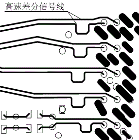
[0026] as attached figure 2 As shown in the schematic diagram of the logical structure of the high-speed interconnection terminal matching of the present invention, the design method of the high-speed interconnection terminal matching is to connect the common mode choke coil (common mode chokes) and the phase compensation circuit to the final receiving end (download) of the high-speed differential signal line; The high-speed differential signal line is first connected to the common-mode choke coil to suppress the common-mode voltage, so that the common-mode voltage on the high-speed differential signal line is 0, and then connected to the phase compensation circuit to realize phase compensation, so that the high-speed differential signal line The phase of the signal on is matched, and finally connected to the final receiving end.

[0027] as attached image 3 As s...


PUM


Abstract

The invention particularly relates to a high-speed internet terminal matching design method. According to the high-speed internet terminal matching design method, the final receiving end of a high-speed differential signal line is connected with a common-mode choking coil and a phase compensation circuit; the high-speed differential signal line is first connected to the common-mode choking coil for inhibiting common-mode voltage, so that the common-mode voltage of the high-speed differential signal line is 0; then the high-speed differential signal line is connected to the phase compensation circuit for realizing phase compensation, so that the signal phases of the high-speed differential signal line are matched; and finally the high-speed differential signal line is connected to the final receiving end. According to the high-speed internet terminal matching design method, the common-mode choking coil is adopted for inhibiting the common-mode voltage, so that the common-mode voltage of the high-speed differential signal line is 0; the phase compensation circuit is adopted for realizing phase compensation, so that the signal phases of the high-speed differential signal line are matched; and therefore, unnecessary isometric windings are reduced, wire arrangement space is saved, the winding time of design personnel is greatly shortened, the product design and development time is shortened, and the research and development cycle is shortened.

Description

technical field [0001] The invention relates to the technical field of research and development of server motherboards, in particular to a design method for high-speed interconnection terminal matching. Background technique [0002] Differential transmission is a signal transmission technology that uses a numerical value to represent the difference between two physical quantities. In layman's terms, the driving end sends two signals of equal value and opposite phase, and the signal receiving end compares the difference between the two voltages to determine whether the sending end is sending a logic 0 or a logic 1. [0003] Different from the traditional practice of one signal line and one ground line, differential transmission transmits signals on both differential signal lines. The signals on these two differential signal lines have equal amplitudes and opposite phases. The signals transmitted on these two lines are differential signals. The farther the signal source and ...

Claims


Application Information

Patent Timeline
IPC IPC(8): G06F13/40
CPCG06F13/4068
Inventor 李永翠王林
Owner LANGCHAO ELECTRONIC INFORMATION IND CO LTD
Learn More