Fan and motor thereof

A motor and casing technology, applied in the field of coil setting of fans and their inner rotor motors, can solve the problems of difficult start, reduce fan air volume, magnetic flux leakage, etc., reduce production and manufacturing costs, improve motor efficiency, and simplify winding way effect

A motor and casing technology, applied in the field of coil setting of fans and their inner rotor motors, can solve the problems of difficult start, reduce fan air volume, magnetic flux leakage, etc., reduce production and manufacturing costs, improve motor efficiency, and simplify winding way effect

CN101582616BActive Publication Date: 2012-01-04DELTA ELECTRONICS INC

Image

  • Fan and motor thereof
  • Fan and motor thereof
  • Fan and motor thereof

Examples


Embodiment Construction

[0021] A fan and its motor according to preferred embodiments of the present invention will be described below with reference to related drawings, wherein the same elements will be described with the same reference symbols.

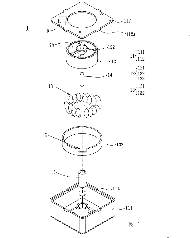
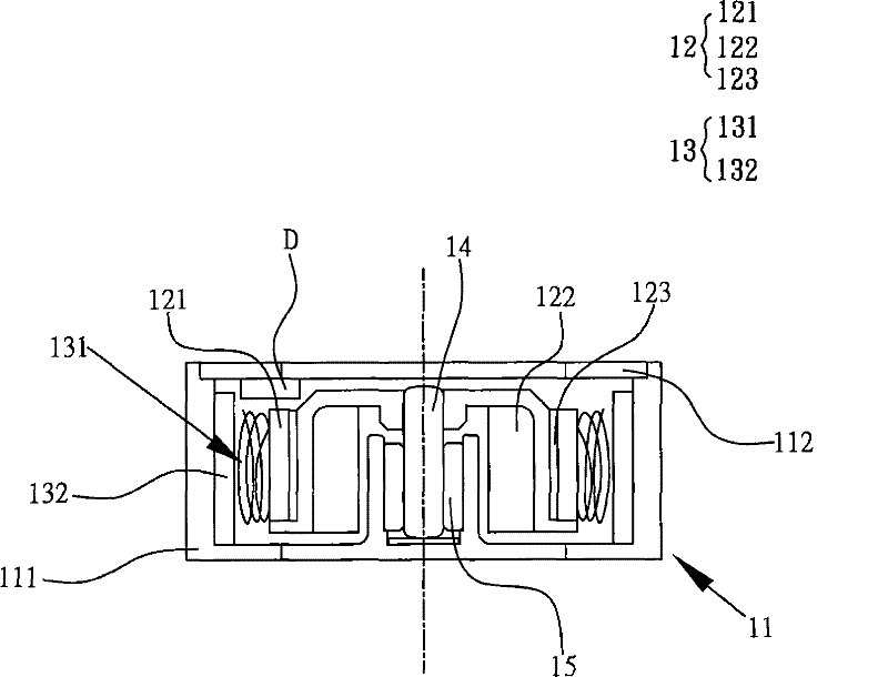
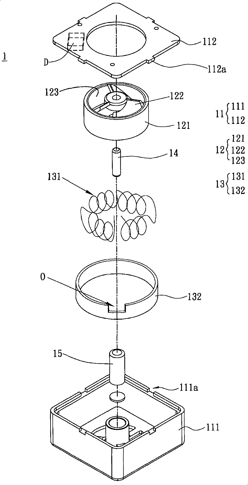
[0022] Please refer to figure 1 As shown, a fan 1 of the present invention includes an inner rotor motor, and the inner rotor motor includes a casing 11 , a rotor assembly 12 and a stator assembly 13 . The rotor set 12 has a rotor 121, the rotor has a fan blade 122 accommodated in the casing 11, and another magnetic element is sleeved on the rotor 121, the rotor 121 can also be directly made of magnetic materials, so that it can save As a demagnetizing element, a first magnetically conductive element 123 is arranged on the inner ring of the rotor 121 to provide a closed magnetic circuit. The stator group 13 is accommodated in the housing 11 corresponding to the rotor group 12. The stator group 13 includes A coil 131 , the coil 131 is formed by a continuo...


PUM


Abstract

The invention discloses a fan and a motor thereof. The fan comprises an interior rotor motor. The motor comprises a casing, a rotor group and a stator group, wherein the rotor group is provided with arotor. The rotor is provided with a fan blade arranged in the casing, the stator group corresponding to the rotor group is arranged in the casing and comprises a coil, and the coil is formed in sucha way that a continuous wire material surrounds the rotor after forming a flat helical structure along the circumferential direction of the rotation of the motor by taking the radial direction of themotor as a center in a helical winding mode.

Description

technical field [0001] The invention relates to a fan and its motor, in particular to a fan and the coil arrangement of the inner rotor motor thereof. Background technique [0002] The volume of the current fans used in electronic devices or electronic systems tends to be thinner and smaller. In the limited volume of products, it is necessary to improve the heat dissipation performance of the fans. In order to improve the heat dissipation performance of the fan, one of the important improvement methods is to adjust the fan blade area of ​​the fan. [0003] Generally speaking, fan motors can be classified into outer rotor motors and inner rotor motors according to the arrangement of the rotor structure and the stator structure. [0004] The existing inner rotor fan uses an inner rotor motor to drive the fan blades to rotate. However, since the silicon steel sheets and the winding wires of the stator structure occupy most of the space between the fan frame and the fan blades,...

Claims


Application Information

Patent Timeline
04 Jan 2012
Publication
CN101582616B
IPC
H02K21/02; H02K21/14; H02K3/04; H02K1/27; H02K11/00; F04D25/08; H02K11/20
Inventors
ι™ˆεŽšεŠ©; 蔑水发