dc‑dc converter with linear overtemperature protection circuit

An over-temperature protection circuit, DC-DC technology, applied in the direction of output power conversion devices, instruments, electrical components, etc., can solve the problems of abnormal operation of DC-DC converters, noise effects, etc., to avoid abnormal operation, The effect of smooth work

Active Publication Date: 2017-09-01
XI AN M3 SEMICONDUCTOR INC
View PDF3 Cites 0 Cited by
  • Summary
  • Abstract
  • Description
  • Claims
  • Application Information

AI Technical Summary

Problems solved by technology

[0004] One of the objectives of the present invention is to provide a DC-DC converter with a linear over-temperature protection circuit to solve the problem of abnormal operation of the DC-DC converter caused by the shutdown of devices by the existing over-temperature protection circuit or the influence of noise on DC -Technical issues with DC converter work

Method used


Image

  • dc‑dc converter with linear overtemperature protection circuit
  • dc‑dc converter with linear overtemperature protection circuit
  • dc‑dc converter with linear overtemperature protection circuit

Examples


Embodiment 1

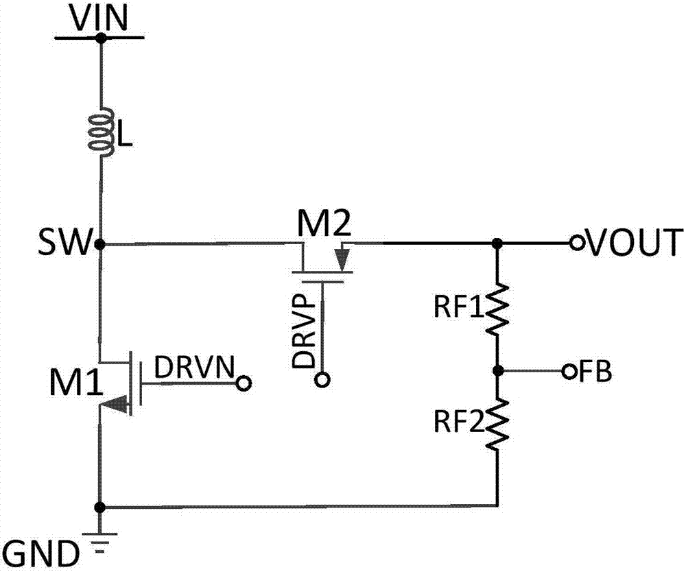
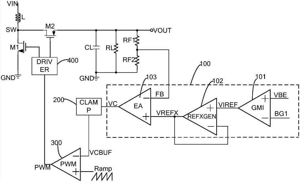
[0072] Such as image 3 As shown, the present invention provides a DC-DC converter with a linear over-temperature protection circuit including a DC-DC boost circuit part and a feedback circuit part, wherein the feedback circuit part includes: a linear over-temperature protection circuit 100, Clamping circuit 200, PWM signal generating circuit 300, driving circuit 400 and temperature transistor (not shown in the figure);

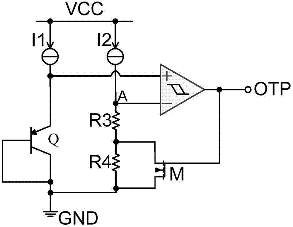
[0073] A temperature transistor, used to generate a junction voltage signal according to the collected temperature of the DC-DC converter;

[0074] A linear over-temperature protection circuit 100, configured to form an error amplification signal according to the junction voltage signal and the first reference voltage signal;

[0075] The clamping circuit 200 is used to limit the maximum value and the minimum value of the error amplification signal to keep the error amplification signal within a fixed voltage range, and form a temperature adjustment signal. ...

Embodiment 2

[0087] Such as Figure 3 ~ Figure 6 As shown, the embodiment of the present invention provides a linear over-temperature protection circuit. The linear protection circuit includes: a linear transconductance amplifier sub-circuit, a reference voltage generation sub-circuit and an error amplifier sub-circuit; wherein,

[0088] The non-inverting input end of the linear transconductance amplification sub-circuit is connected to the junction voltage signal, the inverting input end is connected to the first reference voltage signal, and the output signal end is connected to the non-inverting input end of the reference voltage generation sub-circuit, which is used for combining the junction voltage signal with the first reference voltage signal. A reference voltage signal forms a temperature deviation signal that maintains a linear relationship with temperature;

[0089] The inverting input end of the reference voltage generating subcircuit is connected to the output signal end, and...


PUM


Abstract

The invention relates to a DC-DC converter with a linear over-temperature protection circuit. The DC-DC converter includes: a temperature triode, which generates a junction voltage signal on the basis of the collected temperature of the DC-DC converter; a linear over-temperature protection circuit, which forms an error amplification signal on the basis of the junction voltage signal and a first voltage reference signal; a clamp circuit, which limits the maximum value and the minimum value of the error amplification signal to enable the error amplification signal to keep within a fixed voltage range, and also forms a temperature adjusting signal; a PWM signal generation circuit, which forms a PWM pulse signal on the basis of the temperature adjusting signal and a slope signal; and a drive circuit, which generates, on the basis of the PWM pulse signal, a drive signal to control the output power of a DC-DC boost circuit. According to the embodiment, the output power of the DC-DC converter can be linearly adjusted so that the inner temperature keeps constant, thereby preventing an overly high temperature from affecting the converter and an internal chip. Moreover, noise caused by frequent turning on and turning off of the chip in the prior art is avoided, and thus the DC-DC converter can function steadily.

Description

technical field [0001] The invention relates to the technical field of electronic circuits, in particular to a DC-DC converter with a linear over-temperature protection circuit. Background technique [0002] figure 1 It shows a synchronous step-up DC-DC (Direct Current, DC power supply) converter structure, the input signal VIN is connected to the SW terminal through the inductor L, and the low-side NMOS transistor is connected between the SW terminal and the common terminal GND; when the When the low-side NMOS transistor is turned on, the inductor L is charged. The high-end PMOS transistor is connected between the SW terminal and the output terminal VOUT; when the high-end PMOS transistor is turned on, the inductor L is discharged. By controlling the switching action of the low-end NMOS transistor and the high-end PMOS transistor, the inductor L is charged and discharged, thereby outputting a stable DC voltage signal. When abnormal conditions such as high ambient tempera...

Claims


Application Information

Patent Timeline
Patent Type & Authority Patents(China)
IPC IPC(8): H02M3/155H02M1/32
Inventor 娄诺孟庆达惠惠
Owner XI AN M3 SEMICONDUCTOR INC
Why Eureka
Try Eureka