Foreign object detection device, foreign object detection method, and non-contact charging system
A foreign object detection and detection circuit technology, which is applied in the direction of measuring devices, radio wave measurement systems, circuit devices, etc., can solve the problems of foreign object detection performance degradation, foreign object detection, detection coils and other problems
- Summary
- Abstract
- Description
- Claims
- Application Information
AI Technical Summary
Problems solved by technology
Method used
Image

Examples
Embodiment approach 1
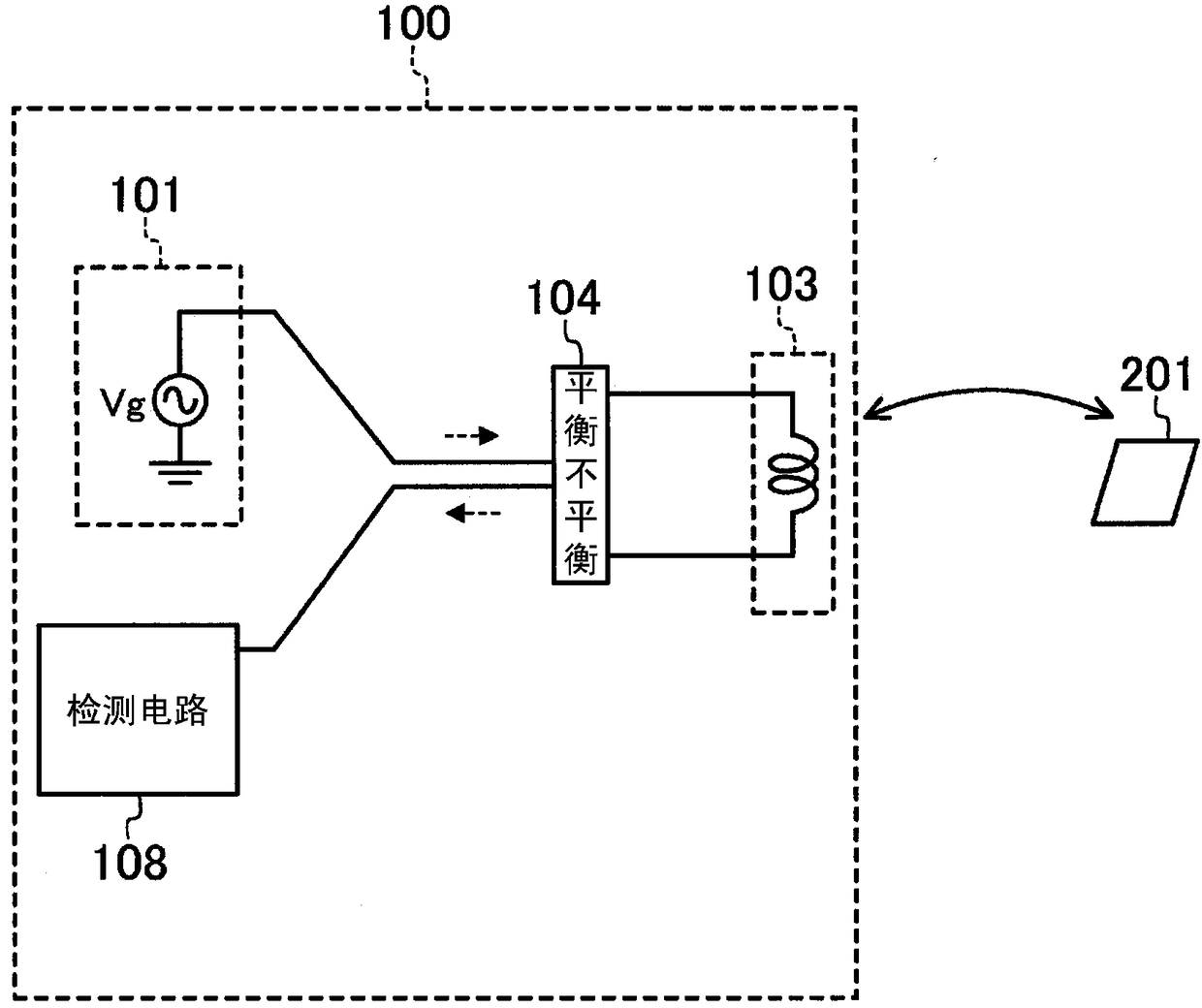
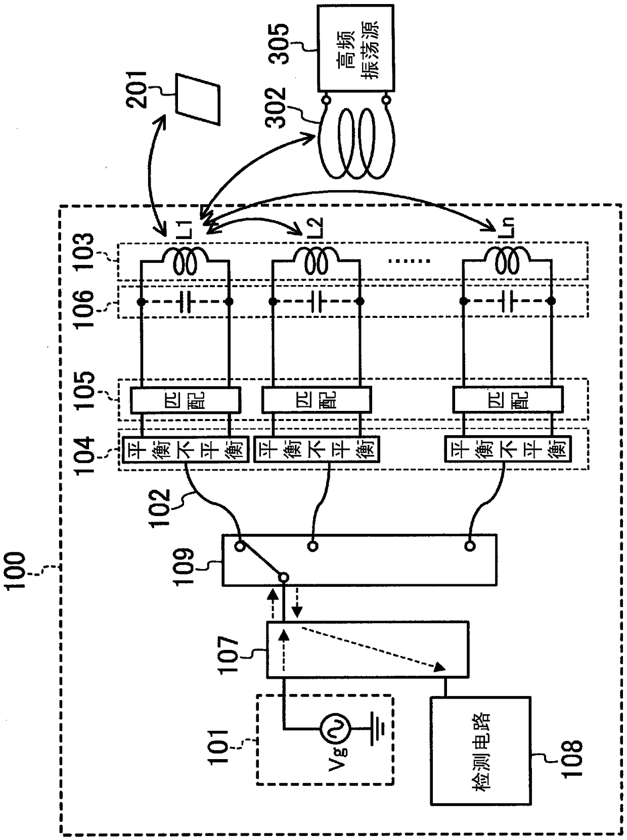
[0038] figure 2 It is a figure which shows the detailed structure of the foreign object detection apparatus 100 in Embodiment 1. The transmission circuit 101 generates high-frequency power (high-frequency power) of a predetermined frequency, and outputs the high-frequency power to a detection coil 103 described later via a coaxial cable 102 or the like that transmits a high-frequency unbalanced signal. The coaxial cable 102 is a transmission line in which the periphery of the central conductor is shielded with an outer conductor. The detection coil 103 is a coil that generates a high-frequency magnetic field for detecting the metal foreign object 201, and is composed of n (n is an integer equal to or greater than 2) coils L1, L2, . . . , Ln arranged.
[0039] The balun conversion circuit 104 is connected to a matching circuit 105 described later and the coaxial cable 102 , converts an unbalanced signal input from the coaxial cable 102 into a balanced signal, and outputs the ...
Embodiment approach 2
[0062] Below, yes Figure 7 Prevention of circuit damage in the foreign object detection device 200 shown will be described.
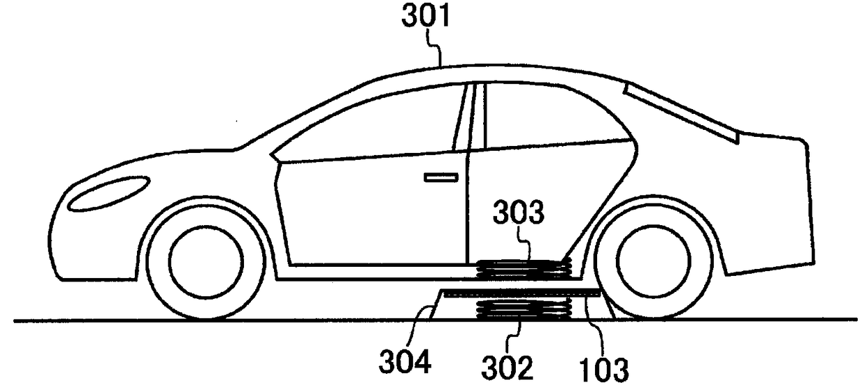
[0063] like figure 2 In this way, a non-contact charging system is configured by combining the foreign object detection device 100 , the power transmission coil 302 , and the high-frequency oscillation source 305 described in the first embodiment. The high-frequency oscillation source 305 supplies high-frequency power of a predetermined frequency to the power transmission coil 302 for non-contact charging.
[0064] Since the high-frequency oscillation source 305 transmits high power, if a magnetic field coupling occurs between the detection coil 103 and the power transmission coil 302, high power is input to the transmission circuit 101, the detection circuit 108, and the switch circuit 109, and each circuit is interrupted. risk of destruction. Therefore, the frequency of the high-frequency power output from the transmission circuit 101 is set to a...
Embodiment approach 3
[0068] Below, yes Figure 8 The mutual coupling reduction between the coils which comprise the detection coil 103 in the foreign object detection apparatus 300 shown will be demonstrated.
[0069] like Figure 4 As shown, since the plurality of detection coils 103 are arranged close to each other, mutual coupling occurs respectively. exist figure 2 In this case, when the coil L1 is selected among the detection coils 103 , unselected coils other than the coil L1 are coupled to the coil L1 to induce a current. As a result, the change in received power caused by the metal foreign object 201 becomes small, and the foreign object detection performance deteriorates.
[0070] Therefore, in this embodiment, if Figure 8 As shown, the two terminals of the unselected detection coil 103 are short-circuited by the short-circuit circuit 111 . In addition, the case where the short-circuit circuit 111 is provided between the matching circuit 105 and the parasitic capacitance 106 is sho...
PUM
 Abstract
Description
Claims
Application Information
 - R&D
- Intellectual Property
- Life Sciences
- Materials
- Tech Scout
- Unparalleled Data Quality
- Higher Quality Content
- 60% Fewer Hallucinations
Browse by: Latest US Patents, China's latest patents, Technical Efficacy Thesaurus, Application Domain, Technology Topic, Popular Technical Reports.
© 2025 PatSnap. All rights reserved.Legal|Privacy policy|Modern Slavery Act Transparency Statement|Sitemap|About US| Contact US: help@patsnap.com