
Lubrication apparatus, lubrication method and rolling oil for metal plate strip cold rolling

A technology for metal strips and lubricating equipment, applied in metal rolling, metal rolling, metal processing equipment, etc., can solve problems such as low recovery rate and energy consumption, achieve simple adjustment methods, reduce rolling oil consumption, and improve surface quality. uniform effect

Active Publication Date: 2015-10-21
张正秀
View PDF17 Cites 6 Cited by
  • Summary
  • Abstract
  • Description
  • Claims
  • Application Information

AI Technical Summary

Problems solved by technology

However, the recovery rate is still not high because the traditional rolling method will generate a large amount of waste liquid; even if the recovery rate is high, the recovery process will consume a lot of energy

Method used


Image

  • Lubrication apparatus, lubrication method and rolling oil for metal plate strip cold rolling
  • Lubrication apparatus, lubrication method and rolling oil for metal plate strip cold rolling
  • Lubrication apparatus, lubrication method and rolling oil for metal plate strip cold rolling

Examples


Embodiment 1

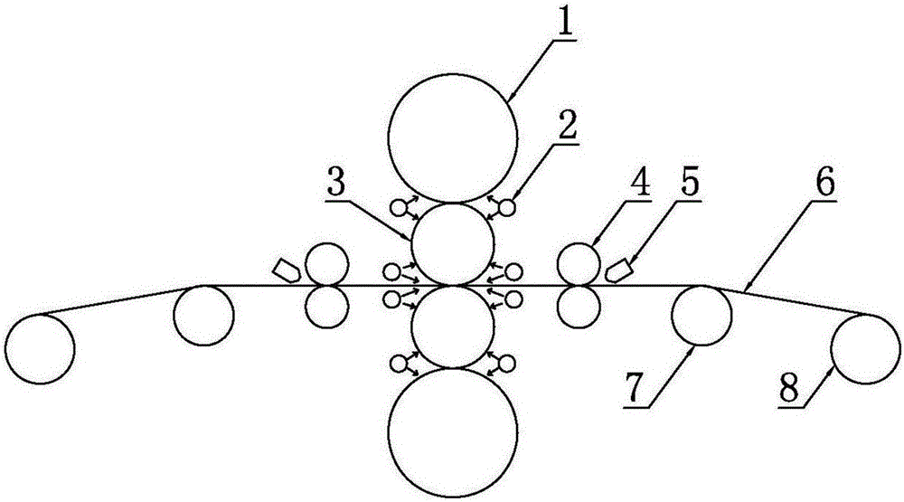
[0035] Such as figure 1 As shown, a lubricating equipment for cold rolling of metal strips includes a backup roll 1, a work roll 3 and an auxiliary roll 4, the backup roll 1 and the work roll 3 are interlocked and connected, and the metal strip 6 passes through the two auxiliary rolls 4 in sequence The gap between the two work rolls 3, because the metal strip 6 passes through the work roll 3 under high temperature and high pressure, therefore, beside the gap between the back-up roll 1 and the work roll 3, the two An emulsion nozzle 2 is installed beside the gap between the work rolls 3; in order to provide lubrication, a rolling oil atomizing injection device 5 is installed next to the gap between the two auxiliary rolls 4 of the present invention, and the rolling oil atomizing injection device 5 Spray atomized rolling oil between the gaps of the auxiliary rolls 4 or on the metal strip 6 to achieve lubrication.

[0036] Such as figure 1 In the reversible rolling mill shown, ...

Embodiment 2

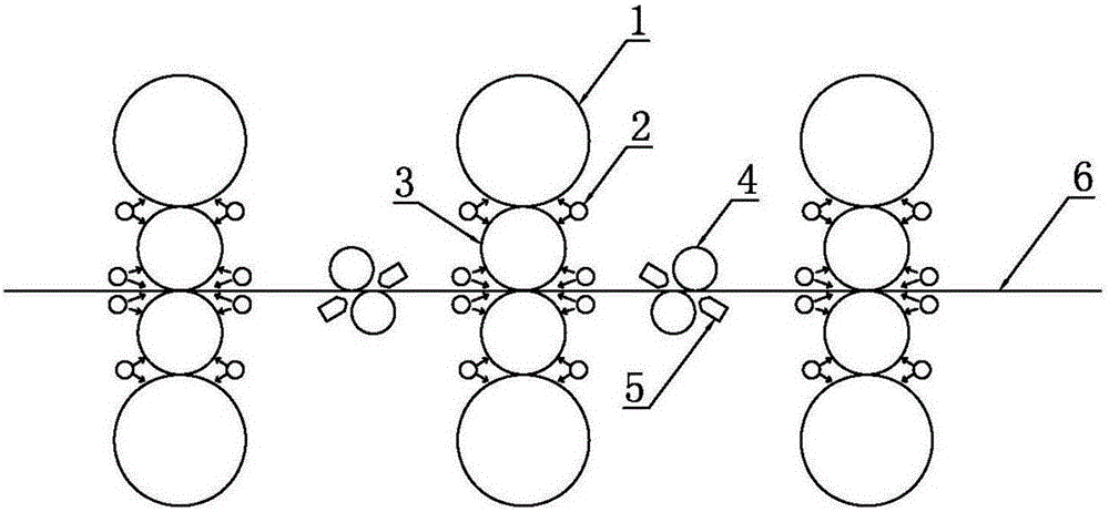
[0039] The application principle of embodiment two is basically the same as that of embodiment one, the difference is that embodiment two is a continuous rolling mill, and the two auxiliary rolls 4 are respectively a dam roll and a tension roll. The rolls are staggered. The rolling oil atomization injection device 5 sprays the gap between the dam roll and the metal strip 6, the gap between the tension roll and the metal strip 6, and the surface of the metal strip 6, so as to realize the cleaning of the metal strip during the rolling process. 6. Lubrication.

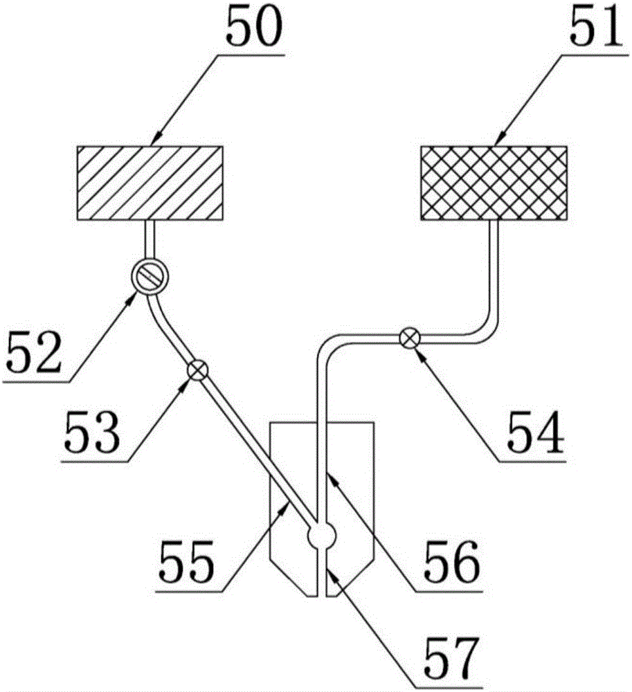
[0040] The invention also discloses a lubricating method for cold rolling of metal strips. The rolling oil is atomized by an air compressor 51 and a rolling oil atomizing spray device 5, and the atomized rolling oil is atomized by the rolling oil The injection device 5 sprays on the auxiliary roll 4 or the surface of the steel strip to lubricate the metal strip 6 before cold rolling. After the metal strip 6 with rolling ...


PUM


Abstract

The invention discloses a lubrication apparatus for metal plate strip cold rolling. The lubrication apparatus includes a rolling oil atomization and spray device which is arranged beside a gap between auxiliary rollers; an oil-way passage, a gas-way passage and a fog-way passage are formed in the rolling oil atomization and spray device; after being communicated with each other, the oil-way passage and the gas-way passage are connected with the fog-way passage; and the outlet end of the fog-way passage is provided with an atomization nozzle. The invention also discloses a method for lubrication by using the above lubrication apparatus and rolling oil used in the method. With the spay mode in the invention adopted, the consumption of the rolling oil is 50% to 80% of that of an existing spay mode, and little metal powder and waste oil sludge are generated in a rolling process, and energy consumption for recovery processing can be decreased, and environmental protection can be benefitted; and the oil flow adjustment method of the rolling oil is simple and convenient.

Description

technical field [0001] The invention relates to the technical field of metal strip processing, and more specifically relates to a lubricating device, a lubricating method and rolling oil for cold rolling of metal strips. Background technique [0002] Lubrication is often required during the rolling process of basic metal strips such as steel, aluminum or copper, while for the cold rolling process, process lubrication and cooling must be implemented. [0003] At present, emulsion is used to provide lubrication during cold rolling, and the composition ratio of emulsion is 2%-4% rolling oil and 96%-98% desalted water. The emulsion nozzle sprays emulsion to the roll gap area at a flow rate of 1000-2000 liters per minute to play the role of lubrication; at the same time, sprays emulsion to the working roll, intermediate roll and backup roll at a flow rate of about 3000 liters per minute to play a role. cooling effect. The amount of emulsion used is large, the volume of the tank...

Claims


Application Information

Patent Timeline
Patent Type & Authority Applications(China)
IPC IPC(8): B21B45/02C10M169/04C10N40/24C10N30/06
CPCY02P70/10
Inventor 张正秀
Owner 张正秀
Learn More