Trailer bogie

A technology for bogies and trailers, applied in the field of trailer bogies, which can solve the problems of inconvenient installation and disassembly of magnetic rail hangers, small space, and difficulty in making magnetic rail hangers

Active Publication Date: 2015-10-21
GUANGZHOU ELECTRICAL LOCOMOTIVE
View PDF7 Cites 14 Cited by
  • Summary
  • Abstract
  • Description
  • Claims
  • Application Information

AI Technical Summary

Problems solved by technology

[0003] In the patent document whose application number is 201220355120.X and the filing date is 2012.7.20, a B-type subway axle disk brake trailer bogie is disclosed. The bogie includes a frame, and a brake mounting seat is provided on the frame beam. The brake mounting seat extends horizontally and horizontally outward from the beam, and is provided with a mounting hole at the extension end of the brake mounting seat. The brake mounting seat is used to install the braking device. This frame structure, the brake mounting seat It is a cantilever structure, so the rigidity of the brake mounting seat is not good. In addition, it is necessary to use fasteners such as screws to install the brake device. Therefore, it is inconvenient to install and disassemble the brake device. If only one If the brake device is installed with the brake mounting base, the stability of the brake device is not good.
[0004] For the magnetic track brake device, the traditional magnetic track brake device is installed on the frame. In this installation method, wh

Method used


Image

  • Trailer bogie
  • Trailer bogie
  • Trailer bogie

Examples


Embodiment Construction

[0033] The present invention will be further described in detail below in conjunction with the accompanying drawings and specific embodiments.

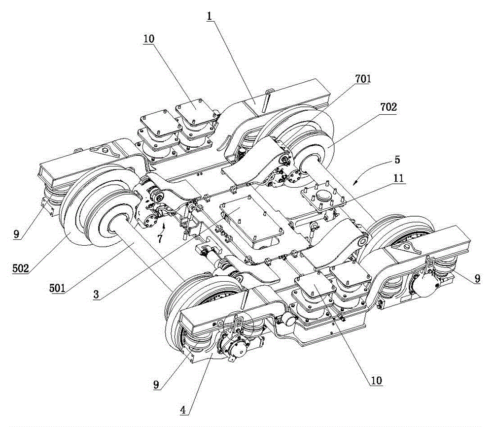
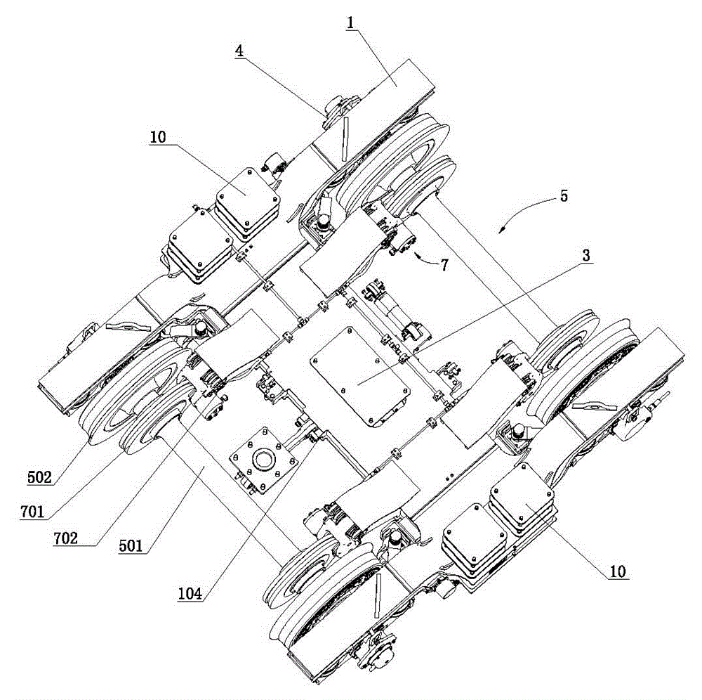
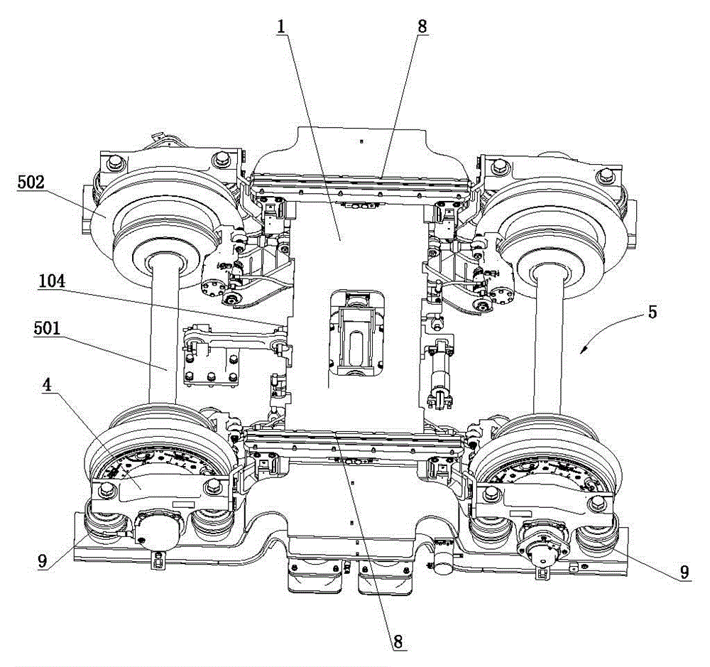
[0034] Such as Figure 1 to Figure 6 As shown, the trailer bogie includes a frame 1, a transverse stop seat 3, an axle box 4, a wheel set 5, a braking device 7, a magnetic rail braking device 8, a primary suspension 9, a secondary suspension 10, and a traction device 11.

[0035] Such as Figure 7 to Figure 9 As shown, the frame 1 includes side beams 101 and cross beams 103 .

[0036]Side beam 101 is made up of two, and is parallel to each other, and described side beam 101 is formed box-shaped structure by base plate, cover plate, side plate and end plate, can reduce the weight of side beam, in by base plate, cover plate, side plate Ribs can be welded in the side sill formed by the end plate to improve the strength of the side sill 101; as Figure 7 As shown, the middle part of the side beam 101 is depressed downward to form a con...


PUM


Abstract

The invention discloses a trailer bogie which comprises a frame, an axle box, a wheel set, a primary suspension, a secondary suspension, a brake device, a magnetic track brake device and a traction device. The frame comprises side beams and a transverse beam. Brake installation bases are arranged on the transverse beam. The brake installation bases include the upper brake installation base and the lower brake installation base. The upper brake installation base comprises a brake side plate and a brake top plate. The brake side plate extends upwards in an inclined manner from the transverse beam, is bent outwards and then extends towards the outer side. An open slot larger than the semicircle is formed in the outer end of the brake side plate. The brake top plate extends outwards from the transverse beam, is bent to extend upwards in an inclined manner and then is bent to extend towards the outer side. A cavity is formed between the brake side plate and the brake top plate. The magnetic track brake device comprises a first magnetic track fixing plate and a second magnetic track fixing plate. The trailer bogie can improve the rigidity of the brake installation bases, the brake device is conveniently assembled and disassembled, the installation stability of the brake device is good, the magnetic track brake device is conveniently assembled and disassembled, and the cost of the magnetic track brake device is lowered.

Description

technical field [0001] This invention relates to trailer trucks. Background technique [0002] Compared with the power bogie, the trailer bogie generally does not have a driving device. The trailer bogie is used to install the trailer body. devices etc. [0003] In the patent document whose application number is 201220355120.X and the filing date is 2012.7.20, a B-type subway axle disk brake trailer bogie is disclosed. The bogie includes a frame, and a brake mounting seat is provided on the frame beam. The brake mounting seat extends horizontally and horizontally outward from the beam, and is provided with a mounting hole at the extension end of the brake mounting seat. The brake mounting seat is used to install the braking device. This frame structure, the brake mounting seat It is a cantilever structure, so the rigidity of the brake mounting seat is not good. In addition, it is necessary to use fasteners such as screws to install the brake device. Therefore, it is inconv...

Claims


Application Information

Patent Timeline
IPC IPC(8): B61F5/00B61F5/52B61H7/08
CPCB61F5/00B61F5/52B61H7/08
Inventor 蒋宽李芾李涛安琪陈信才涂立波黄赫
Owner GUANGZHOU ELECTRICAL LOCOMOTIVE
Why Eureka
Try Eureka