Indoor temperature adjusting system

A technology for regulating system and indoor temperature, applied in air conditioning system, heating system, hot water central heating system, etc., can solve the problems of large resistance of floor heating pipes, affecting heating effect, affecting heating effect of floor heating, etc.

Inactive Publication Date: 2015-10-21
宁波奉化吉涛电器有限公司
View PDF11 Cites 4 Cited by
  • Summary
  • Abstract
  • Description
  • Claims
  • Application Information

AI Technical Summary

Problems solved by technology

[0003] There are some deficiencies in the existing floor heating system: 1) Traditional heating systems usually use 16mm-20mm pipes for flooring operations, and the distance between adjacent parallel pipes is 20cm-25cm, and large-diameter pipes need to be heated And the energy of urging the water flow to circulate is large, which makes the energy consumption high, thereby increasing the cost of use; and because the distance between adjacent pipes is large, the heat emitted from the pipes is uneven, which affects the heating effect of floor heating , relatively uncomfortable; 2) At present, the heating source of floor heating for single-family families or unit floors is air energy, that is, heat pumps. In the process of heating water, the proper efficiency cannot be achieved

Method used


Image

  • Indoor temperature adjusting system
  • Indoor temperature adjusting system

Examples


Embodiment Construction

[0013] The present invention will be further described below in conjunction with the accompanying drawings.

[0014] In the description of the present invention, it should be understood that the terms "upper", "lower", "inner", "outer", etc. indicating orientation or positional relationship are based on the positional relationship described in the drawings, and are only for the convenience of describing the present invention Or simplify the description instead of indicating a specific orientation that must have.

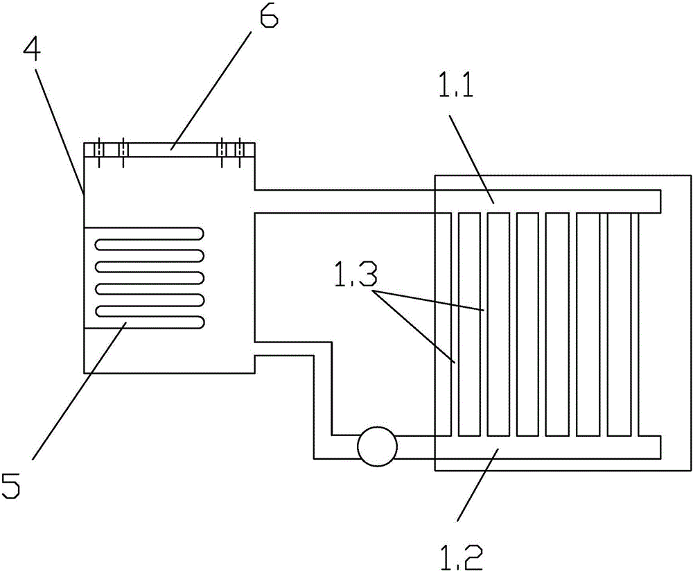
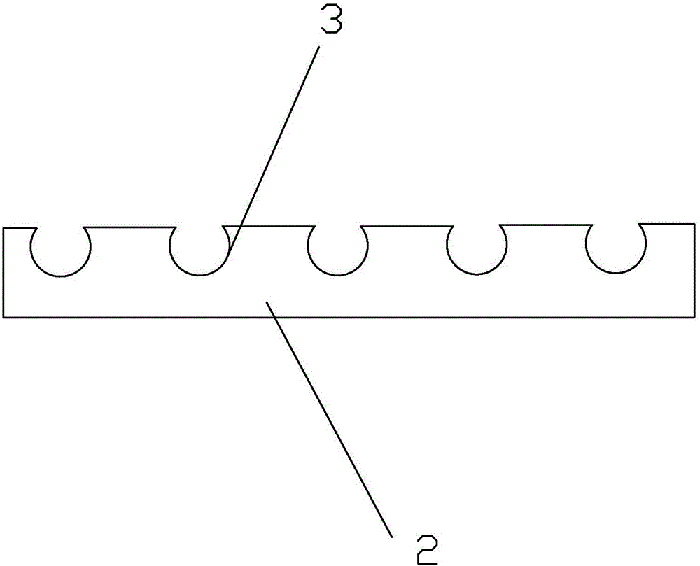
[0015] Such as figure 1 , figure 2 As shown, a kind of indoor temperature regulation system, it comprises heating or cooling system and the indoor heat exchange tube that arranges at least on indoor ground, and heating or cooling system comprises the box body 4 that antifreeze liquid is housed, heating or cooling The host and the heat exchanger 5 for heating or cooling the antifreeze liquid in the box 4, the heat exchanger 5 is located in the box 4, the heat excha...


PUM

PropertyMeasurementUnit
Diameteraaaaaaaaaa

Abstract

An indoor temperature adjusting system comprises a heating or refrigerating system and indoor heat exchange pipes. The heating or refrigerating system comprises a tank (4) containing anti-freezing liquid, a heating or refrigerating main machine and a heat exchanger (5) used for heating or refrigerating the anti-freezing liquid in the tank (4). The heat exchanger (5) is located in the tank (4) and connected with the heating or refrigerating main machine. A water pump is arranged on a connecting pipe of the tank (4) and the heat exchange pipes. The indoor heat exchange pipes comprise a liquid inflow pipe (1.1), a liquid outflow pipe (1.2) and multiple flow division pipes (1.3) which are arranged between the liquid inflow pipe (1.1) and the liquid outflow pipe (1.2) in parallel. The diameter of each flow division pipe (1.3) ranges from 3 mm to 6 mm. The distance between every two adjacent flow division pipes (1.3) ranges from 3 cm to 5 cm. The two ends of each flow division pipe (1.3) are communicated with the liquid inflow pipe (1.1) and the liquid outflow pipe (1.2). The tank (4) is communicated with the liquid inflow pipe (1.1) and the liquid outflow pipe (1.2).

Description

technical field [0001] The invention relates to the field of floor heating, in particular to an indoor temperature regulating system suitable for single households or small groups. Background technique [0002] At present, floor heating has become the main heating method for residential buildings and factories in the north, mainly for central heating; in the south, more and more families have begun to use floor heating for indoor heating. [0003] There are some deficiencies in the existing floor heating system: 1) Traditional heating systems usually use 16mm-20mm pipes for flooring operations, and the distance between adjacent parallel pipes is 20cm-25cm, and large-diameter pipes need to be heated And the energy of urging the water flow to circulate is large, which makes the energy consumption high, thereby increasing the cost of use; and because the distance between adjacent pipes is large, the heat emitted from the pipes is uneven, which affects the heating effect of floo...

Claims


Application Information

Patent Timeline
IPC IPC(8): F24F5/00F24D3/10
CPCF24F5/00F24D3/10F24F2221/40
Inventor 周旭毓
Owner 宁波奉化吉涛电器有限公司
Why Eureka
Try Eureka