
Superheat section and condensing section-separately arranged evaporation type condensation heat exchanger and method thereof

An evaporative condensing and condensing section technology, used in evaporators/condensers, refrigerators, refrigeration components, etc., can solve the problems of increased volume, reduced cooling water temperature, increased floor space, etc., and improved heat exchange efficiency , the effect of reducing the heat exchange area and increasing the total heat transfer coefficient

Inactive Publication Date: 2015-10-21
SOUTH CHINA UNIV OF TECH
View PDF7 Cites 2 Cited by
  • Summary
  • Abstract
  • Description
  • Claims
  • Application Information

AI Technical Summary

Problems solved by technology

This kind of condenser performs secondary heat and mass exchange between air and water in the packing heat exchange layer, which greatly reduces the temperature of cooling water, thereby improving the heat transfer per unit area of ​​the condensing coil, but the volume increases and the occupied area increases.

Method used


Image

  • Superheat section and condensing section-separately arranged evaporation type condensation heat exchanger and method thereof
  • Superheat section and condensing section-separately arranged evaporation type condensation heat exchanger and method thereof
  • Superheat section and condensing section-separately arranged evaporation type condensation heat exchanger and method thereof

Examples


Embodiment

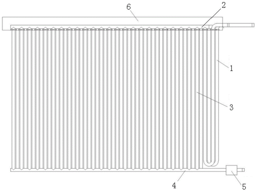
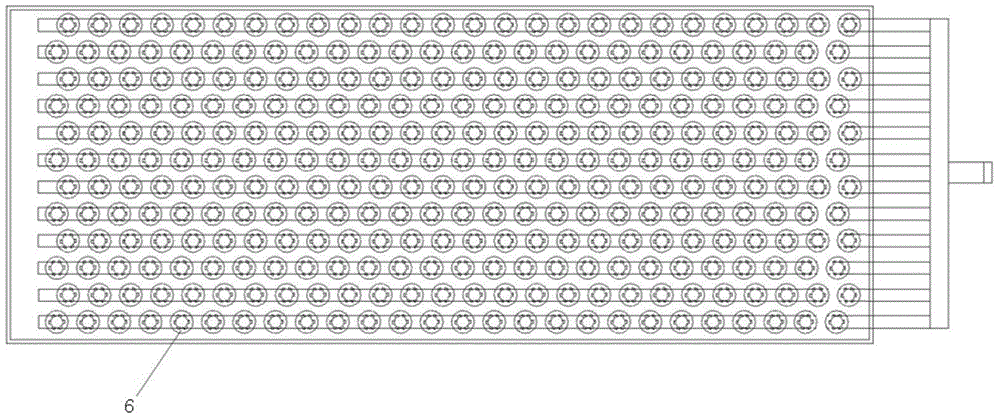
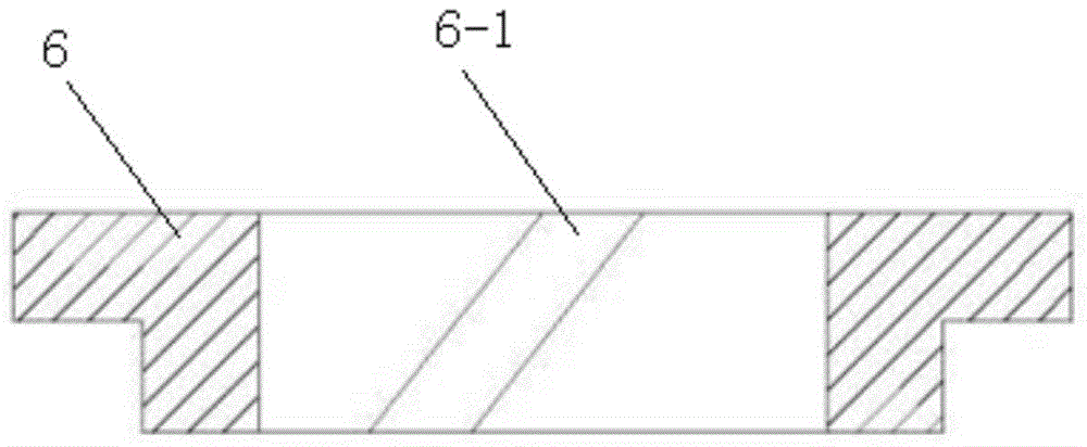
[0029] Such as Figures 1 to 4 shown. The evaporative condensation heat exchanger with separate superheating section and condensing section of the present invention includes a serpentine superheated steam cooling section 1, a horizontally arranged upper gas collecting pipe 2, a horizontally arranged lower liquid collecting pipe 4, and vertical falling film condensation heat exchange tubes 3;

[0030] There are multiple vertical falling film condensing heat exchange tubes 3, and they are distributed between the upper gas collector 2 and the lower liquid collector 4 at intervals;

[0031] The upper end of the vertical falling film condensing heat exchange tube 3 is connected to the upper air collector 2;

[0032] The lower end of the vertical falling film condensation heat exchange tube 3 is connected to the lower liquid collection pipe 4;

[0033] The port of the lower liquid collecting pipe 4 is provided with a liquid sealing device 5;

[0034] The serpentine superheated s...


PUM


Abstract

The invention discloses a superheat section and x condensing section-separately arranged evaporation type condensation heat exchanger and a method thereof. The superheat section and condensing section-separately arranged evaporation type condensation heat exchanger includes an S-shaped superheated vapor cooling section, a horizontally-arranged upper gas collection pipe, a horizontally-arranged lower liquid collection pipe and vertical falling film condensation heat exchange pipes; a plurality of vertical falling film condensation heat exchange pipes are adopted and are distributed between the upper gas collection pipe and the lower liquid collection pipe at intervals; the S-shaped superheated vapor cooling section is U-shaped pipe; the inlet of the U-shaped pipe is connected with a compressor; the outlet of the U-shaped pipe is connected with the upper gas collection pipe; the upper ends of the vertical falling film condensation heat exchange pipes are respectively sleeved with a flow guide and water distributor with an oblique groove; and cooling water flows out through the oblique grooves along a tangential direction and is distributed on the outer surfaces of the vertical falling film condensation heat exchange pipes. The thickness of refrigerant condensed fluid films in the vertical falling film condensation heat exchange pipes of the heat exchanger is decreased, and the quantity of accumulated refrigerant fluid is decreased, and refrigerant charge can be decreased; and a refrigerant-side condensation heat exchange coefficient can be increased, and heat exchange efficiency can be improved.

Description

technical field [0001] The invention relates to an evaporative condenser, in particular to an evaporative condensation heat exchanger with separate superheating sections and condensation sections and a method thereof. Background technique [0002] The evaporative condenser mainly uses the latent heat of vaporization when the cooling water sprayed outside the heat exchange tube evaporates to condense the refrigerant vapor in the coil. Combining the secondary cooling and heat exchange process of the traditional water-cooled and air-cooled cooling towers into one, eliminating unnecessary cooling towers and heat exchangers in the intermediate process, it has high heat transfer efficiency, compact structure, small volume, and circulation Less water reduces the initial investment of equipment, and it is increasingly popularized in power, chemical, food, refrigeration and other industries, and has achieved great success. The evaporative condenser is mainly composed of three parts:...

Claims


Application Information

Patent Timeline
Patent Type & Authority Applications(China)
IPC IPC(8): F25B39/04
CPCF25B39/04F25B2339/041
Inventor 刘金平陈志勤许雄文
Owner SOUTH CHINA UNIV OF TECH
Learn More