

Dispersive confocal detection device and dispersive confocal detection system
A dispersive confocal and detection device technology, applied in the field of optical detection, can solve the problems of low detection accuracy, poor stability and reliability, complex structure, etc., and achieve the effects of high detection accuracy, good stability and reliability, and simple structure
- Summary
- Abstract
- Description
- Claims
- Application Information
AI Technical Summary
Problems solved by technology
Method used
Image

Examples
Embodiment 1
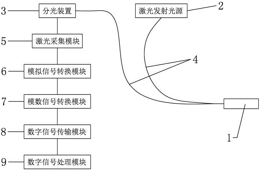
[0023] Embodiment one, such as figure 1 As shown, a dispersion confocal detection device includes a laser sampling pen 1, a laser emitting light source 2, and a spectroscopic device 3. The light output position of the laser emitting light source 2 is connected to the optical sampling pen through a transmission fiber 4, and the incident light of the spectroscopic device 3 The position is connected to the optical sampling pen through the transmission optical fiber 4, and a laser acquisition module 5 is installed at the light output position of the spectroscopic device 3.
[0024] Further, the dispersion confocal detection device also includes a digital signal processing module 9, the laser acquisition module 5 is equipped with an analog signal conversion module 6, and an analog-to-digital signal is installed between the digital signal transmission module 8 and the analog signal conversion module 6. The conversion module 7 and the digital signal transmission module 8 , the analog...
Embodiment 2
[0027] Embodiment two, such as figure 1 As shown, a dispersion confocal detection system includes a laser sampling pen 1, a laser emitting light source 2, a spectroscopic device 3, a fixed mounting frame, and a moving platform that can be relatively movably installed under the fixed mounting frame. The laser sampling pen 1 Installed on a fixed mounting frame, the light output position of the laser emitting light source 2 is connected to the optical sampling pen through the transmission fiber 4, the light input position of the spectroscopic device 3 is connected to the optical sampling pen through the transmission fiber 4, and the light output position of the spectroscopic device 3 is equipped with Laser acquisition module 5.
[0028] Further, the dispersion confocal detection system also includes a digital signal processing module 9, the laser acquisition module 5 is equipped with an analog signal conversion module 6, and an analog-to-digital signal is installed between the di...
PUM
 Abstract
Description
Claims
Application Information