
Microchannel plate and preparation method thereof

A micro-channel plate and micro-channel technology, applied in cold cathode manufacturing, electrode system manufacturing, discharge tube/lamp manufacturing, etc., can solve the problems of output, weak spatial resolution of micro-channel plates, etc. Effect

Active Publication Date: 2015-10-21
CHINA BUILDING MATERIALS ACAD
View PDF5 Cites 8 Cited by
  • Summary
  • Abstract
  • Description
  • Claims
  • Application Information

AI Technical Summary

Problems solved by technology

It has been found that even if the deposition depth of the electrode material is increased, the escape angle of the multiplied electrons of the microchannel plate at the output end of the microchannel plate is between 3° and 5°, which cannot be output parallel to the axis of the microchannel, causing the microchannel plate When the electrons output from the output end reach the coupling device (such as a fluorescent screen) with a certain distance from the microchannel plate, a divergence effect will occur, so that the spatial resolution of the existing microchannel plate is relatively weak

Method used


Image

  • Microchannel plate and preparation method thereof
  • Microchannel plate and preparation method thereof
  • Microchannel plate and preparation method thereof

Examples


Embodiment Construction

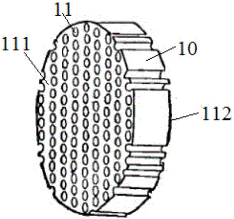
[0046] In order to further explain the technical means and effects of the present invention to achieve the intended purpose of the invention, the specific implementation, characteristics and effects of a microchannel plate and its preparation method according to the present invention will be described below in conjunction with the preferred embodiments. , detailed below.

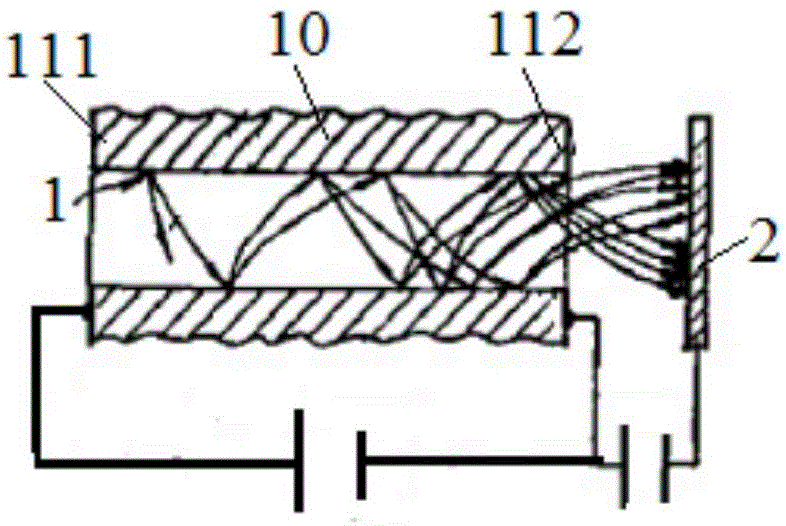
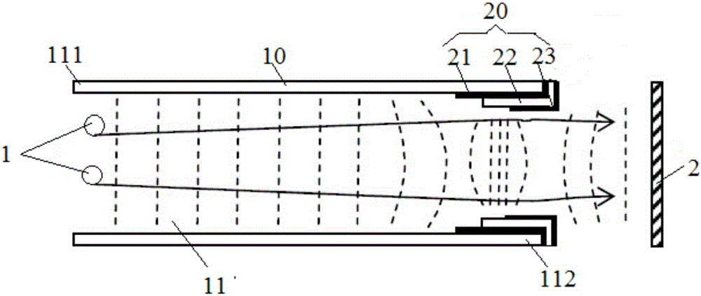
[0047] Such as figure 1 As shown, the structure schematic diagram of the microchannel plate provided by the first embodiment of the present invention. Specifically, combine figure 1 , figure 2 and image 3It can be known that the micro-channel plate provided in this embodiment includes: a substrate 10 and at least one thin film 20 . Substrate 10 is provided with a plurality of micro-channels 11, and one end of micro-channels 11 is input end 111, and the end face of described input end 111 is coated with conductive material (as nickel-chromium alloy, nichrome-iron or chromium etc. conductive material), d...


PUM

PropertyMeasurementUnit
Thicknessaaaaaaaaaa

Abstract

The invention discloses a microchannel plate and a preparation method thereof and relates to a field of micro-optical element manufacture technology. According to the invention, an escape angle of multiplication electron beams output from an output terminal of the microchannel plate is controlled, the coupling efficiency of the microchannel plate is improved and spatial discrimination capability is enhanced. The main technical scheme of the invention is that the microchannel plate includes a base board and at least one film; the base board is provided with a plurality of micro-channels; the input terminal whose end face is coated with conducting material is disposed on one end of each micro-channel; the output terminal is disposed on the other end of each micro-channel; an end of the film is formed on the end part of the output terminal through coating while the other end of the film is formed on the inner wall of the output terminal; and the film includes a first conducting layer, a medium layer and a second conducting layer formed on the output terminal successively through coating, wherein the lengths of the parts of first conducting layer, the medium layer and the second conducting layer on the inner wall of the micro-channel decrease in sequence.

Description

technical field [0001] The invention relates to the technical field of manufacturing micro-optical elements, in particular to a micro-channel plate and a preparation method thereof. Background technique [0002] A microchannel plate is a two-dimensional electron multiplier with an array of fine hollow tubes. A microchannel plate has about millions or even tens of millions of hollow microchannels. Because microchannel plates have the properties of electronic gain and spatial resolution, microchannel plates are widely used in detection devices and low-light imaging devices. The spatially high-resolution energy of the microchannel plate determines the quality of low-light imaging detection and identification. How to improve the spatial resolution of microchannel plates has always been a hot and difficult research topic. [0003] In the prior art, the angle at which electrons escape is usually restricted by adjusting the depth at which the electrode material at the output end ...

Claims


Application Information

Patent Timeline
IPC IPC(8): H01J43/04H01J9/00
Inventor 黄永刚
Owner CHINA BUILDING MATERIALS ACAD
Learn More