S-waveband communication-in-motion double-frequency circularly polarized micro-strip antenna and array thereof

A technology of microstrip antenna and communication in motion, which is applied to the combination of antenna units, antennas, and radiating element structures with different polarization directions. Effect

Inactive Publication Date: 2015-10-21
常州吉赫射频电子技术有限公司
View PDF6 Cites 6 Cited by
  • Summary
  • Abstract
  • Description
  • Claims
  • Application Information

AI Technical Summary

Problems solved by technology

Compared with the traditional parabolic antenna, the microstrip antenna has many advantages such as low profile, light weight, easy processing, easy array formation, and low cost. It can realize multi-polarization working mode by rationally d

Method used


Image

  • S-waveband communication-in-motion double-frequency circularly polarized micro-strip antenna and array thereof
  • S-waveband communication-in-motion double-frequency circularly polarized micro-strip antenna and array thereof
  • S-waveband communication-in-motion double-frequency circularly polarized micro-strip antenna and array thereof

Examples


specific Embodiment approach 1

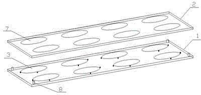
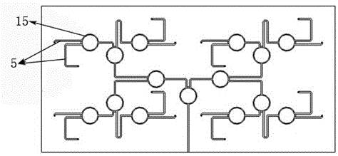
[0037] Specific implementation mode one: to combine figure 1 , image 3 , Figure 4 , Figure 5 with Image 6, the S-band dual-frequency circularly polarized microstrip antenna array of the present invention is made of a three-layer PTFE plate 1 etched with a metal floor 4, a radiation metal sheet 3, and a feed network 9 and a single layer of a parasitic metal sheet 7 etched with The PTFE plate 1 is supported and connected by nylon column pins 8 . The microstrip feeder 5 and the radiating metal sheet 3 are electrically connected through the metal via 6; the opening 10 corresponding to the center axis of the metal via 6 on the floor has an aperture larger than that of the metal via 6, and the metal floor 4 is electrically insulated from the metal via 6. The central axes of the corresponding radiating metal sheets 3 and the parasitic metal sheets 7 coincide respectively. The radius R3 of the metal via 6 = 0.8 mm; the radius R4 of the opening 10 corresponding to the centra...

specific Embodiment approach 2

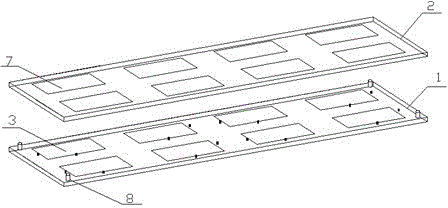
[0039] Specific implementation mode two: combine figure 2 , image 3 , Figure 4 , Figure 5 with Image 6 , the S-band dual-frequency circularly polarized microstrip antenna array of the present invention is made of a three-layer PTFE plate 1 etched with a metal floor 4, a radiation metal sheet 3, and a feed network 9 and a single layer of a parasitic metal sheet 7 etched with The PTFE plate 1 is supported and connected by nylon column pins 8 . The microstrip feeder 5 and the radiating metal sheet 3 are electrically connected through the metal via 6; the metal floor 4 corresponds to the opening 10 at the central axis of the metal via 6, and the aperture is larger than the diameter of the metal via 6. The metal floor 4 and the metal via 6 are electrically connected. insulation. The central axes of the corresponding radiating metal sheets 3 and the parasitic metal sheets 7 coincide respectively. The radius R3 of the metal via 6 = 0.8 mm; the radius R4 of the opening 10...


PUM

PropertyMeasurementUnit
Thicknessaaaaaaaaaa
Thicknessaaaaaaaaaa
Radiusaaaaaaaaaa

Abstract

The invention relates to an S-waveband communication-in-motion double-frequency circularly polarized micro-strip antenna and an array thereof. The micro-strip antenna includes a metal floor, a dielectric substrate, a radiation metal sheet, a parasitic metal sheet and a micro-strip feeder line, and the micro-strip antenna array includes a metal floor, a dielectric substrate, a radiation metal sheet, a parasitic metal sheet and a micro-strip feed network. The S-waveband double-frequency circularly polarized micro-strip antenna and the array thereof introduces the parasitic element on the basis of a traditional double-fed circularly polarized micro-strip antenna and an array thereof, thereby greatly expanding the working bandwidth, and enabling excellent impedance characteristic and radiation characteristic to be realized in a double-frequency-band range of uplink 1.98 to 2.01 GHz and downlink 2.17 to 2.20 GHz of an S waveband.

Description

technical field [0001] The invention relates to an S-band moving-in-motion dual-frequency circularly polarized microstrip antenna and an array thereof. Background technique [0002] Mobile Communication is the abbreviation of "Moving Satellite Ground Station Communication System". In the satellite communication antenna system, the multi-frequency antenna can improve the communication capacity and reduce the construction cost of the ground station, so it is widely used. Compared with the traditional parabolic antenna, the microstrip antenna has many advantages such as low profile, light weight, easy processing, easy array formation, and low cost. It can realize multi-polarization working mode by rationally designing the radiation unit structure and feeding mode; however , usually, the impedance bandwidth of the microstrip antenna is very narrow (2-4%), which severely limits its application in the field of multi-frequency / broadband communication. Contents of the invention ...

Claims


Application Information

Patent Timeline
IPC IPC(8): H01Q13/08H01Q1/38H01Q21/24
Inventor 邱景辉张鹏宇
Owner 常州吉赫射频电子技术有限公司
Why Eureka
Try Eureka