
Hybrid multi-terminal direct current power transmission system and inverter station and control method thereof

A technology of power transmission system and multi-terminal direct current, which is applied in the direction of inverter with reversible conversion equipment, power transmission AC network, etc., can solve the problems of power transmission drop, overall system failure, reliability problems, etc., to reduce overhead and enhance robustness performance, cost reduction

Active Publication Date: 2015-10-21
HITACHI ENERGY SWITZERLAND AG
View PDF4 Cites 20 Cited by
  • Summary
  • Abstract
  • Description
  • Claims
  • Application Information

AI Technical Summary

Problems solved by technology

However, in traditional grid-commutated converter-based multi-terminal DC transmission systems, this centralized control method based on fast communication between rectifier stations and inverter stations usually causes reliability problems
During the failure of fast communication equipment, the failure of any converter station in the system may cause power transmission decline or overall system failure due to failure to adjust the control parameters in time

Method used


Image

  • Hybrid multi-terminal direct current power transmission system and inverter station and control method thereof
  • Hybrid multi-terminal direct current power transmission system and inverter station and control method thereof
  • Hybrid multi-terminal direct current power transmission system and inverter station and control method thereof

Examples


Embodiment Construction

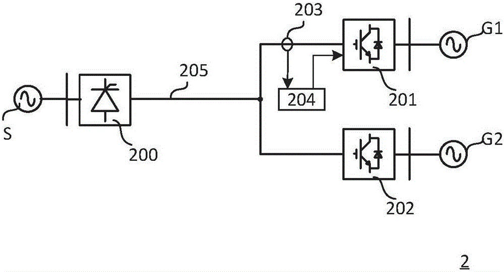
[0021] figure 2 A hybrid multi-terminal direct current transmission system according to an embodiment of the present invention is shown. like figure 2 As shown, the hybrid multi-terminal DC power transmission system 2 includes: a rectifier station 200 , two inverter stations 201 , 202 , a voltage detection component 203 and a VSC control system 204 . The converter of the rectification station 200 is composed of LCC. The LCC of the rectifier station 200 rectifies the AC power from the power source S into DC power with a desired DC voltage value and feeds the DC power to the DC transmission line 205 .

[0022] The converters of the inverter stations 201 and 202 are composed of VSCs. The VSCs of the inverter stations 201, 202 invert the DC power from the DC transmission line 205 into AC power and inject it into the AC grid G1, G2. Each VSC includes a first DC terminal for electrically coupling the DC transmission line 205 and a second DC terminal for electrically coupling t...


PUM


Abstract

The invention provides a hybrid multi-terminal direct current power transmission system and an inverter station and a control method thereof. The hybrid multi-terminal direct current power transmission system comprises a rectification station comprising an LCC, at least two inverter stations comprising VSCs, a voltage detection component and a VSC control system on the side of the inverter stations. Under the condition that a detected direct current voltage value is lower than a predetermined value, a part of the VSCs are controlled to be switched from an inversion mode to a rectification mode and the rest of the VSCs are controlled to main the inversion mode and the VSC working in the rectification mode are controlled so that the direct current voltage thereof basically maintain the predetermined value. The detection for the drop of the direct current voltage of direct current transmission lines and the control of the operation modes of the VSCs of the inverter stations are performed on the side of the inverter stations, so that the rectification station and the inverter stations can separately take corresponding actions (decentralized control) so solve the problem that some converter stations cannot cut the power supply after the rectification station retreats from a hybrid multi-terminal direct current system without rapid inter-station communication.

Description

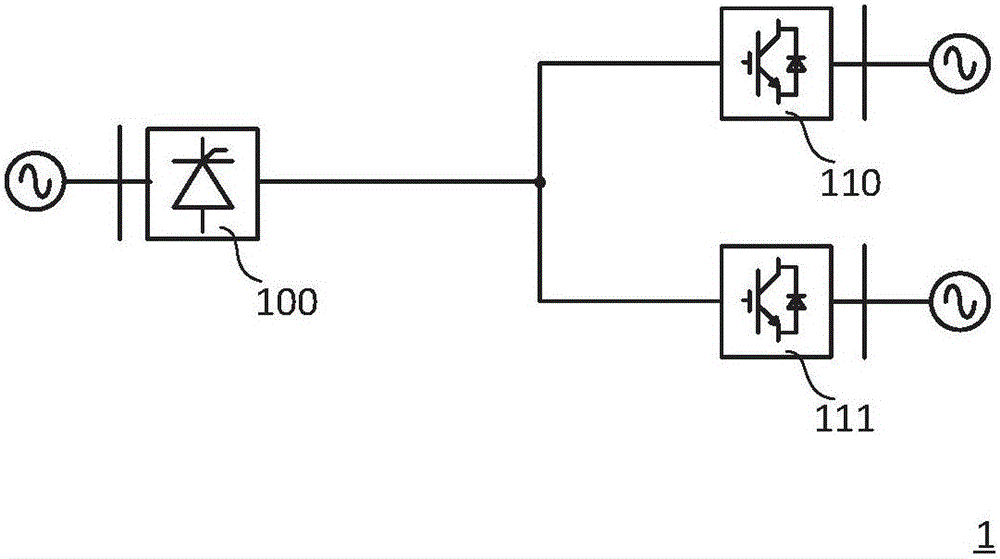
technical field [0001] The present invention relates to a multi-terminal direct current transmission system, more specifically, to a hybrid multi-terminal direct current transmission system, an inverter station and a control method thereof. Background technique [0002] figure 1 A conventional hybrid MTDC transmission system is shown. like figure 1 As shown, the hybrid multi-terminal direct current transmission system 1 includes a line commutated converter 100 (LCC: Line Commutated Converter) as a rectifier station and at least two voltage source converters 110, 111 (VSC: Voltage Source Converter). The hybrid HVDC multi-terminal transmission system combines the respective advantages of the conventional HVDC transmission system (LCC HVDC) and the light-duty HVDC transmission system (VSC HVDC), while abandoning the disadvantages of the two HVDC transmission systems. For example, the hybrid multi-terminal DC transmission system has the advantages of low cost and low power l...

Claims


Application Information

Patent Timeline
IPC IPC(8): H02J3/36H02M7/72
CPCY02E60/60
Inventor 苑春明杨晓波姚大伟杨超
Owner HITACHI ENERGY SWITZERLAND AG
Learn More