Abrasive flow micropore polishing device

A processing device and abrasive flow technology, applied in the field of abrasive flow processing and micro-hole precision machining, can solve the problems of low cutting energy, poor micro-hole processing efficiency, impact, etc., and achieve the effect of improving utilization rate

Active Publication Date: 2015-10-28
CHANGCHUN UNIV OF SCI & TECH
View PDF7 Cites 20 Cited by
  • Summary
  • Abstract
  • Description
  • Claims
  • Application Information

AI Technical Summary

Problems solved by technology

However, the processing efficiency of the current abrasive flow machining micropore device is limited. Only a simple pressurized cylinder or a pressurized cylinder is used to pressurize the abrasive flow, so that the abrasive flow can cut the micropore surface of the workpiece, realizing The precision machining of micro holes, this method only relies on the pressurized cylinder to give the impact cutting energy of the abrasive flow, and the abrasive flow is due to the flow resistance in the pipeline, when the abrasive flow flows into the micropores of the workpiece, the abrasive particles More than half of the flow energy of the flow is often lost, resulting in too low impact and cutting energy, and the efficiency of microhole machining becomes poor, especially for slender microholes. The abrasive flow has basically lost the impact cutting on the second half of the microholes. Therefore, how to provide a high-performance, high-efficiency abrasive that can apply additional vibration energy to the abrasive flow The particle flow micro-hole processing device plays an extremely important role in processing slender holes, and can realize the development of micro-hole processing promotion

Method used


Image

  • Abrasive flow micropore polishing device

Examples


Embodiment Construction

[0019] The present invention will be described in detail below in conjunction with the accompanying drawings. However, it should be understood that the accompanying drawings are provided only for better understanding of the present invention, and they should not be construed as limiting the present invention.

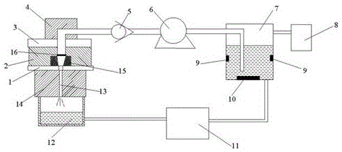
[0020] Such as figure 1 As shown, the present invention provides an abrasive particle flow micropore polishing processing device, which includes a workpiece support seat 1, a pressurized vibration seat 2, an upper support 3, an adapter 4, a high-pressure jet pump 6, and an abrasive flow supply box 7 and the abrasive particle flow collection box 12, characterized in that the workpiece 14 to be processed is supported and arranged below the workpiece support seat 1, the pressurized vibration seat 2 is arranged above the workpiece support seat 1, and the upper support The seat 3 is arranged above the pressurized vibration seat 2, the upper support 3 is connected with an ad...


PUM


Abstract

The invention provides an abrasive flow micropore polishing device. The device comprises a workpiece supporting base, a pressurization vibration base, an upper bracket, an adapter, a high-pressure jet pump, an abrasive flow feeding box and an abrasive flow collecting box, wherein an ultrasonic vibrator is arranged at the lower end of an abrasive flow channel in the pressurization vibration base. By arranging the ultrasonic vibrator at the lower end of the abrasive flow channel in the pressurization vibration base, high acceleration energy can be provided for abrasive flow flowing through under the high-frequency vibration of the ultrasonic vibrator, so that more energy is gathered by the abrasive flow and the abrasive flow enters a workpiece; before the abrasive flow enters the workpiece, a certain buffering effect is realized in an abrasive flow channel in the workpiece supporting base, so that the situation that as adverse effect is generated on the workpiece by the abrasive flow with overhigh vibration frequency, the surface quality of workpiece micropores is affected is avoided. A temperature sensor and a heater are arranged inside the abrasive flow feeding box, so that the situation that due to the fact that the viscosity of the abrasive flow is affected by temperature, the machining precision of the micropore workpiece is affected is avoided.

Description

technical field [0001] The invention relates to the technical field of abrasive flow processing, in particular to an abrasive flow micropore polishing processing device, which belongs to the field of micropore precision processing. Background technique [0002] At present, all kinds of micropores have been widely used in aerospace, aviation, military industry, machinery, automatic control, chemical fiber, photoelectric instrumentation, daily use and some cutting-edge products. This situation makes micropore processing attract much attention. Dozens of micro-hole processing methods have been developed in the world today, each of which has its advantages and disadvantages, which mainly depend on the diameter, depth, workpiece material and equipment requirements of the hole. Different processing methods use different materials, different precision, different roughness and different micropore sizes, and all have a certain scope of application. At present, micro-hole machining g...

Claims


Application Information

Patent Timeline
Patent Type & Authority Applications(China)
IPC IPC(8): B24C3/32B24C9/00
CPCB24C3/32B24C9/00
Inventor 李俊烨张若妍张心明王德民许颖刘建河
Owner CHANGCHUN UNIV OF SCI & TECH
Why Eureka
Try Eureka