A kind of automatic retrieving platform and its transportation method

An automatic retrieving and platform technology, applied in the direction of manipulators, program-controlled manipulators, chucks, etc., can solve the problems of unresolved grasping and playback of specified parts, tedious labor intensity, poor repeatability, etc., and achieve large market development value and can be achieved Enhanced control and high versatility

Active Publication Date: 2017-03-08
JIANGSU UNIV
View PDF1 Cites 0 Cited by
  • Summary
  • Abstract
  • Description
  • Claims
  • Application Information

AI Technical Summary

Problems solved by technology

At present, most of the management and distribution of experimental items in chemical laboratories or medical laboratories in schools at home and abroad are managed manually, which is not only cumbersome but also labor-intensive, especially for those more sophisticated instruments, aseptically manipulated pharmaceutical devices, and experimental procedures. The more dangerous chemicals that are easy to damage the experimenter, when obtaining and storing such objects, there is an urgent need for efficient intelligent management and storage methods. However, most of the pneumatic manipulators on the market are controlled by PLC, and the disadvantage is that the repeatability is poor. , does not meet the user needs of modern intelligent management and distribution in the chemical, chemical and medical fields
For example, the patented magnetic adsorption manipulator (CN201310550461.1), when grabbing parts, exerts less pressure on the parts, which is beneficial to protect the parts, but it does not solve the problem of grabbing and replaying the specified parts

Method used


Image

  • A kind of automatic retrieving platform and its transportation method
  • A kind of automatic retrieving platform and its transportation method
  • A kind of automatic retrieving platform and its transportation method

Examples


Embodiment 1

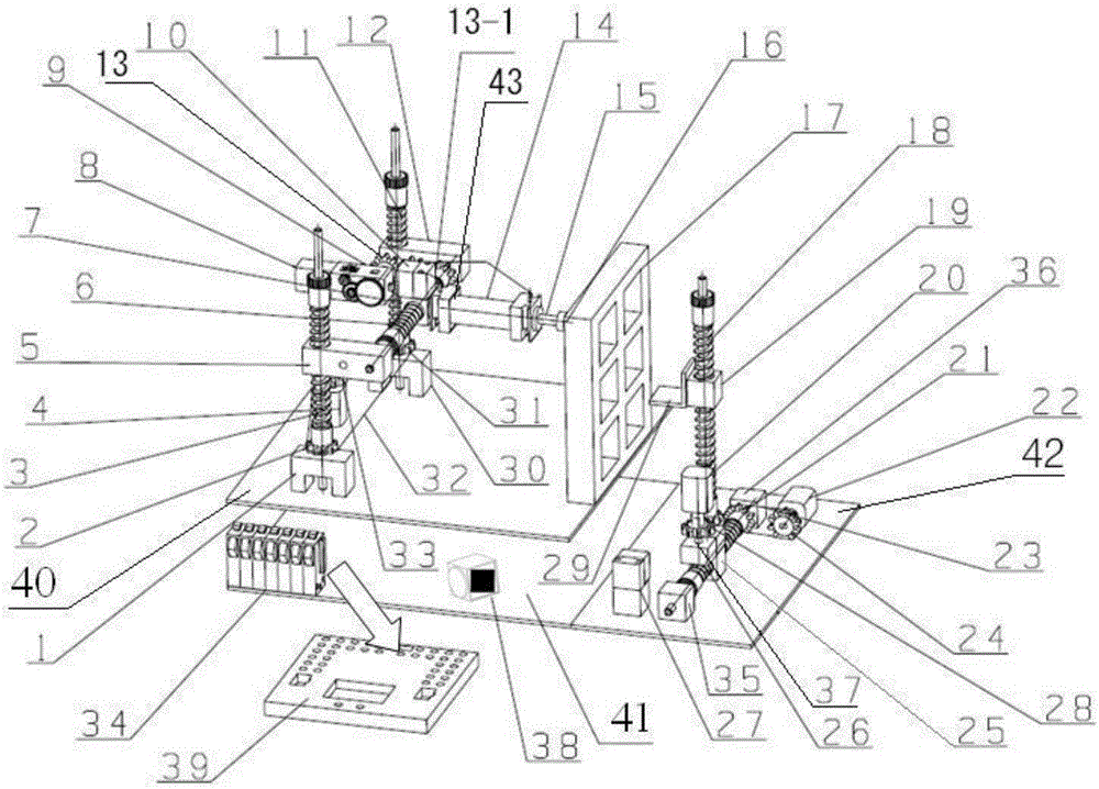
[0036] Such as figure 1 Shown, a kind of automatic retrieving platform comprises upper platform 40, lower platform 41, magnetic force manipulator 43, material cabinet 17, loading moving platform 42, switch 34, controller 39, bar code scanner 27, described upper platform 40 Set directly above the lower platform 41, the lower platform 41 is provided with a switch 34 and an article frame 38; one end of the upper platform 40 is provided with the magnetic manipulator 43, and the other end is provided with the material cabinet 17; The object-carrying platform 42 is connected to the lower platform 41 and is arranged at one end where the material cabinet 17 is located, and the barcode scanner 27 is arranged on the object-carrying platform 42 . The material is packed in the article frame 38, and when picking up the object, it is sucked and placed on the moving platform 42 by pushing the magnetic force manipulator 43, and is transported to the designated position by the moving platform ...

Embodiment 2

[0050] Taking the intelligent warehouse as the realization plan, set the material cabinet 17 to paste red / blue barcodes on the materials at No. 2, white / green barcodes on the materials at No. 4, and white / black barcodes on the materials at No. 6. The color parameters reflected in the color sensor are black, green, blue.

[0051]When picking up the object, press the No. 4 travel switch in the switch 34, the magnetic force manipulator 43 receives the "entry" command, and goes to the No. 4 position of the material cabinet. After the object stage of the platform, the magnetic manipulator resets; at the same time, the object-carrying moving platform transports the No. 4 material to the exit point. When returning the material, place the material (white / green) at the No. 4 position on the barcode scanner 27 at the exit point to wait for scanning, press the electronic switch in the switch 34, and the barcode scanner 27 scans the color barcode at the No. 4 position Identification, whe...

Embodiment 3

[0054] Press the No. 6 travel switch in the switch 34, the magnetic manipulator 43 receives the "entry" command, and moves to the No. 6 matrix grid of the material cabinet 17, and the materials in the No. 6 matrix grid are sucked by the magnetic manipulator 43 and pushed to the load. After moving the platform 42, the magnetic manipulator 43 resets; at the same time, the moving platform 42 carries the material to the exit point. When returning the material, the material (white / black) at the No. 6 position in the moving platform 42 is waiting to be scanned at the exit point, and the electronic switch in the switch is pressed, and the barcode scanner 27 scans and recognizes the color bar code at the No. 6 position. Judging that the color parameter 240≤value≤280, the travel switch No. 6 is triggered, and the magnetic manipulator receives the feedback command of "hand return 6". At this time, the M1 motor 4 and the M2 motor 8 are started, and the magnetic manipulator 43 returns to ...


PUM


Abstract

The invention discloses an automatic material taking platform and a material conveying method thereof. The automatic material taking platform comprises an upper platform body, a lower platform body, a magnetic manipulator, a material cabinet, a carrying dynamic platform body, a switch, a controller and a bar code scanner. A switch and an article frame are arranged on the lower platform body. The magnetic manipulator is arranged at one end of the upper platform body. The material cabinet is arranged at the other end of the upper platform body. The carrying dynamic platform body is connected with the lower platform body and arranged at the end where the material cabinet is located. The bar code scanner is arranged on the carrying dynamic platform body. When materials are taken, the magnetic manipulator is pushed to attract the materials on the material cabinet and place the materials to the carrying dynamic platform body, and the materials are conveyed to an assigned position by the carrying dynamic platform body. When the materials return, the bar code scanner is responsible for scanning bar codes of the materials on the carrying dynamic platform body, the controller sends an instruction, and the materials are conveyed to a material returning position by the carrying dynamic platform body; the materials are attracted and placed to original positions on the material cabinet by the magnetic manipulator; and the functions of taking and classifying the materials are achieved.

Description

technical field [0001] The invention belongs to the field of mechanical transportation, and in particular relates to a pneumatic push magnetic force manipulator for automatic reclaiming. Background technique [0002] Pneumatic magnetic manipulators are not only ideal material handling activities for transportation and distribution in the machinery industry, but are also increasingly used in automobile manufacturing, food packaging and precision instruments. At present, most of the management and distribution of experimental items in chemical laboratories or medical laboratories in schools at home and abroad adopt manual management, which is not only cumbersome but also labor-intensive, especially for those more sophisticated instruments, aseptically manipulated medical devices, and experimental procedures. The more dangerous chemicals that are easy to damage the experimenter, when obtaining and storing such objects, there is an urgent need for efficient intelligent managemen...

Claims


Application Information

Patent Timeline
Patent Type & Authority Patents(China)
IPC IPC(8): B25J15/06B25J9/04B25J9/10B25J11/00B25J19/00
Inventor 蒯苏苏陈寒松张文涛徐路戈文茜
Owner JIANGSU UNIV
Why Eureka
Try Eureka