UAV (unmanned aerial vehicle) assisted landing visual guiding method and airborne system based on ground cooperative mark

A vision-guided, unmanned aerial vehicle technology, applied in the field of flight navigation control, can solve problems such as system reliability decline, increase landing locations and application limitations, and achieve the effects of small errors, simple methods, and improved efficiency and reliability

Inactive Publication Date: 2015-10-28
史彩成
View PDF6 Cites 41 Cited by
  • Summary
  • Abstract
  • Description
  • Claims
  • Application Information

AI Technical Summary

Problems solved by technology

Such methods undoubtedly increase the restrictions on landing locations and app

Method used


Image

  • UAV (unmanned aerial vehicle) assisted landing visual guiding method and airborne system based on ground cooperative mark
  • UAV (unmanned aerial vehicle) assisted landing visual guiding method and airborne system based on ground cooperative mark
  • UAV (unmanned aerial vehicle) assisted landing visual guiding method and airborne system based on ground cooperative mark

Examples


Embodiment 1

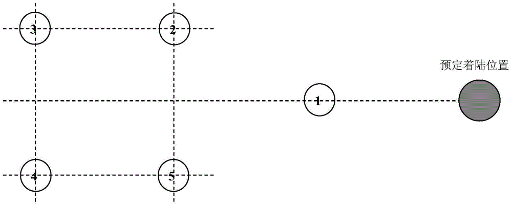
[0107] as attached figure 2 As shown, the ground cooperation sign includes 5 circular luminous bodies, and 4 of them are arranged in a square, and 1 circular luminous body is located outside the square, and this circular luminous body is used as a vertex light. The distance between the center of the predetermined landing position and the centroid of the apex light is set as ΔL.

[0108] Each circular illuminant is a solid illuminant with a diameter of 300mm wound by LED strip lights. Arranged as above to form an arrow shape, it is easy to track and identify the light at the top of the arrow, that is, the vertex light. Each LED lamp is powered by a battery in parallel.

Embodiment 2

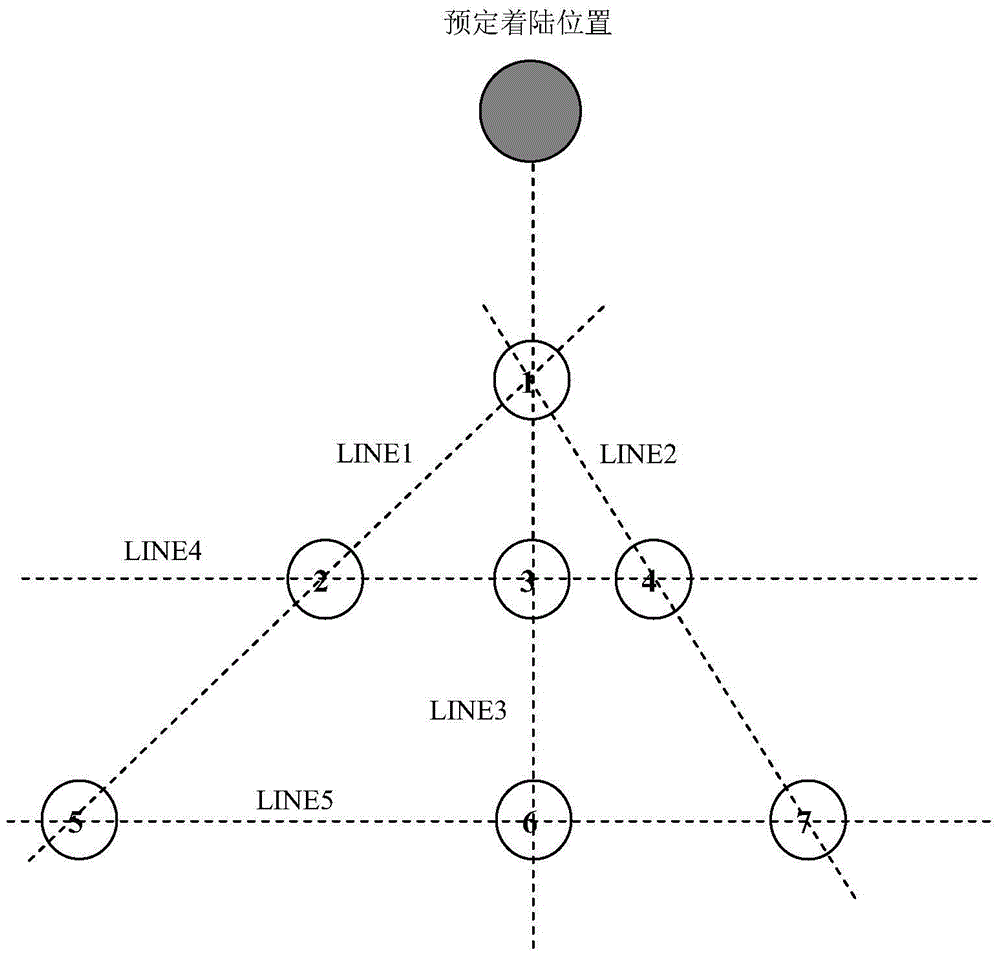
[0110] as attached image 3 As shown, the ground cooperation sign includes 7 circular illuminants, and each circular illuminant is a solid LED light of equal size, of which the LED light No. 1 is the apex light and its radius is R,

[0111] ①The distance between LED light No. 2 and LED light No. 1 is L 1-2 =6.8R, the distance between No. 3 LED lamp and No. 1 LED lamp is L 1-3 =4.8R, the distance between LED lamp No. 4 and LED lamp No. 1 is L 1-4 =5.6R, the distance between LED lamp No. 5 and LED lamp No. 1 is L 1-5 =13.6R, the distance between LED light No. 6 and LED light No. 1 is L 1-6 =9.6R, the distance between LED light No. 7 and LED light No. 1 is L 1-7 =11.2R; said distance is the distance between the centroids of each LED lamp;

[0112] ② The centroids of LED lights No. 1, LED lights No. 2 and LED lights No. 5 are on a straight line and the line is LINE1; the centroids of LED lights No. 1, LED lights No. 3 and LED lights No. 6 are on a straight line and parallel Le...


PUM

PropertyMeasurementUnit
Diameteraaaaaaaaaa

Abstract

The invention discloses a UAV (unmanned aerial vehicle) assisted landing visual guiding method and airborne system based on a ground cooperative mark and belongs to the field of flight navigation control. At least four round luminophors are arranged into the directional ground cooperative mark, and a reserved landing position is set in front of a peak lamp. A UAV hovers at a preset height, each highlight area in each frame of image of an airborne camera is detected, whether the highlight area is one round luminophor or not is judged, then characteristics are compared with ground cooperative mark characteristics stored in a target base in advance and recognized according to the number of the round luminophors and the arrangement relation among the round luminophors, the position of the peak lamp and the preset landing position are acquired, and the UAV is controlled to descend and fly towards the preset landing position and performs target prediction and tracking simultaneously. The ground cooperative mark has less arrangement constraint and high flexibility, various marks are supported for guidance of different landing positions, the UAV assisted landing guidance efficiency and reliability are effectively improved, and GPS (global positioning system) limitation is avoided.

Description

technical field [0001] The invention relates to a visual guidance method and an airborne system for aiding landing of an unmanned aerial vehicle, in particular to a visual guidance method and an airborne system for an unmanned aerial vehicle with ground cooperation mark points. It belongs to the field of flight navigation control. Background technique [0002] Compared with manned aircraft, unmanned aerial vehicles (UAVs) have the characteristics of light weight, low risk of casualties, good maneuverability, and simple cabin design. In addition to their application prospects in the military, they are also gradually showing their prominence in the civilian field . UAV navigation technology mainly includes inertial navigation, radar navigation, GPS navigation, microwave navigation and visual navigation. Among them, with the development of computer vision and image acquisition technology, optical measurement technology, high-speed real-time processing and storage technology, ...

Claims


Application Information

Patent Timeline
IPC IPC(8): B64F1/20B64D45/08
Inventor 史彩成解乃林史其存李秀珍辛怡李勤
Owner 史彩成
Why Eureka
Try Eureka