Wafer fixing device for evaporator

A technology of wafer fixation and vapor deposition machine, which is applied in vacuum evaporation coating, sputtering coating, ion implantation coating, etc. It can solve the problems of difficult locking, many parts to be cleaned, time-consuming and laborious, etc.

Inactive Publication Date: 2015-10-28
苏州工业园区纳米产业技术研究院有限公司
View PDF3 Cites 6 Cited by
  • Summary
  • Abstract
  • Description
  • Claims
  • Application Information

AI Technical Summary

Problems solved by technology

However, using the curved sheet in this way to press the wafer, and then use the shrapnel on the back cover to withstand the wafer, has the following defects: (1) installation is complicated, time-consuming and labor-intensive, especially the first step after installation After the wafer is finished, press an arc-shaped sheet on the wafer, and then install the back cover with shrapnel, and the back cover needs to be locked with a specific nut, because the nut has a large diameter and a thin thickness, so when locking It is more difficult, and at the same time, there is a risk of scratching the front of the wafer due to the large number of installed components; (2) The entire system has a complex structure, many components, and high cost, and there are many components to be cleaned during subsequent maintenance, and the maintenance cost is also low. Very high; (3) When the wafer is fixed, only the elastic force of a shrapnel needs to be fixed, and the wafer and the metal sheet need to be fixed at the same time, there is a risk of the wafer falling off, and the reliability of the entire system is not high

Method used


Image

  • Wafer fixing device for evaporator
  • Wafer fixing device for evaporator
  • Wafer fixing device for evaporator

Examples


Embodiment Construction

[0032] Attached below image 3 to attach Figure 5 As well as examples, specific embodiments of the present invention are described in further detail. The following examples are used to illustrate the present invention, but are not used to limit the scope of the present invention.

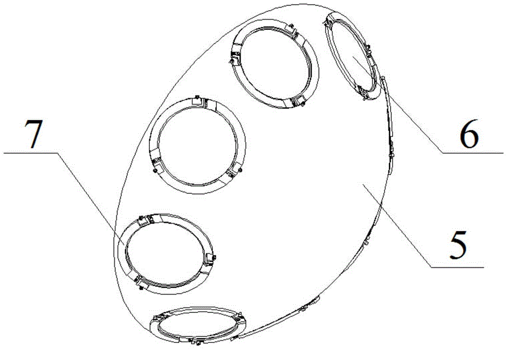
[0033] A wafer fixing device for a vapor deposition machine, comprising a hemispherical support 5, which can also be called a planetary support, and a plurality of through holes 6 are arranged at intervals on the support 5, in order to better implement the present invention In this specific embodiment, the through-holes 6 are evenly spaced along the circumference of the radial section of the bracket 5 and the through-holes 6 are symmetrically arranged in pairs.

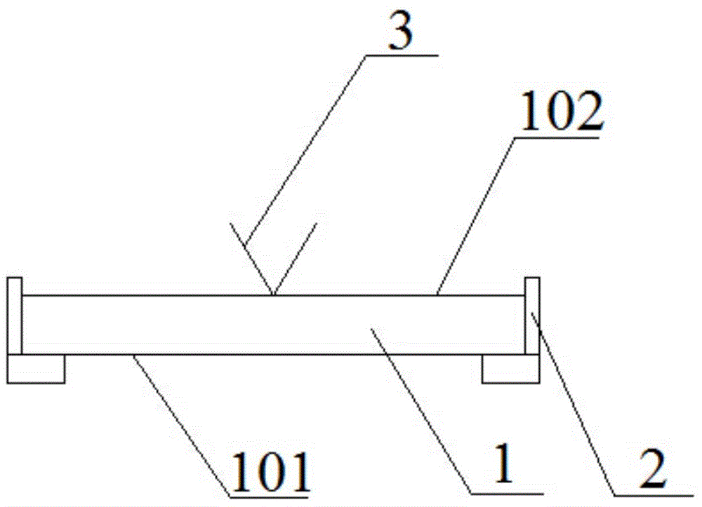
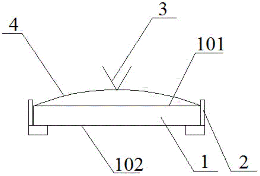
[0034] A wafer ring 7 is fixed on each of the above-mentioned through holes 6 , and in this specific embodiment, the wafer ring 7 can be fixed to the through holes 6 through threaded connectors such as screws. The inner ring of the wafer...


PUM


Abstract

The invention discloses a wafer fixing device for an evaporator. A wafer is fixed onto a support through a wafer ring. An annular concave platform for placing the wafer is formed on the inner circle of the wafer ring. Several elastic fixing parts which can rotate around fixed points are positioned at intervals on the outer circle of the wafer ring. Compression members on the elastic fixing parts act on circumferential edge of the wafer surface in an elastic compression form so as to fix the wafer relative to the annular concave platform. According to the fixing device, the wafer edge fixing mode replaces a middle fixing mode so as to omit a metal cover at the back of the wafer. Thus, the whole fixing device is simple and light. Without locknuts during installation, installation is time-saving and labor-saving, and fittings for cleaning are reduced. By the multi-point fixing mode, stability of the wafer is enhanced. The device provided by the invention can meet requirements for wafer fixing during wafer face and backside evaporation. In addition, wafer installation procedure is greatly simplified, and work efficiency is enhanced.

Description

technical field [0001] The invention relates to a semiconductor device fixing device, in particular to a wafer fixing device for an evaporation machine, and belongs to the field of semiconductor device processing accessories. Background technique [0002] In the semiconductor manufacturing industry, a common preparation process for depositing metal conductive films is the evaporation process. The evaporation machine widely used in this process is the MARK 50 evaporation machine produced by CHA INDUSTRIES in the United States. The evaporation machine is working Usually, the wafer is fixed on a circular support to make it rotate around the fixed axis, and the circular support also revolves along the guide rail. For existing equipment, the original design can only do crystal surface evaporation, that is, fix the crystal surface 101 of the wafer 1 towards the target in the annular groove 2 on the bracket, and then use the back cover with the shrapnel 3 to support the wafer The ...

Claims


Application Information

Patent Timeline
Patent Type & Authority Applications(China)
IPC IPC(8): C23C14/50H01L21/687
Inventor 李文涛王剑杨亮时文礼
Owner 苏州工业园区纳米产业技术研究院有限公司
Why Eureka
Try Eureka