Internal electricity generation system for gas pipeline and automatic control method

A technology for power generation systems and gas pipelines, applied in pipeline systems, collectors, electric vehicles, etc., can solve problems such as reducing the service life of pipelines, inability to install and use monitoring systems, and complicated installations.

Active Publication Date: 2015-10-28
BEIJING GAS GRP +1
View PDF6 Cites 2 Cited by
  • Summary
  • Abstract
  • Description
  • Claims
  • Application Information

AI Technical Summary

Problems solved by technology

[0002] At present, in the process of gas pipeline transportation, since the monitoring and control devices are located in remote areas and far away from the power grid, this will cause power shortage or no power supply for monitoring and testing equipment, and there are hidden dangers. For example, there are many pressure adjustments in the process of natural gas transmission. The station is in a state of power shortage or no power supply due to its remote location, resulting in difficulty in power supply. Due to the remote location of these voltage regulating stations / boxes, it often occurs due to the lack of supply of mains power supply cables, and the necessary lighting and heating in winter. At the same time, because there is no external power supply, the monitoring system cannot be installed and used, and the data cannot be remotely monitored. It is necessary to send inspectors to inspect the site every day, and the uncertain safety hazards of pipe network equipment cannot be discovered in time. the manifestation
[0003] In view of the current power consumption problems of these pressure regulating stations, some experts have proposed to install fluid motors in the pipeline to generate electricity, so as to meet the electricity demand of the pressure regulating stations themselves, but the fluid motors must be installed in the medium and high pressure sections of the natural gas pipeline network, in the low pressure section The pressure energy cannot be utilized, that is, the use of a fluid motor in a pipeline with a slow fluid flow rate cannot meet the demand for power generation, and the fluid motor is directly installed in the main gas pipeline, which has a complex structure and difficult maintenance
In addition, some technicians have proposed an energy-collecting pipeline fluid (flowing water, wind) power generation device, which fully collects the energy of the fluid (flowing water, wind) through a trumpet-shaped energy-collecting pipeline, and then converts the fluid energy into electrical energy through a generator. However, this kind of power generation device needs to remodel the pipeline, which is costly and complicated to install, and the application of this kind of power generation device is relatively limited. There is a great risk of contact
In addition, the temperature will drop after the gas expands to generate electricity. When the low-temperature gas flows back to the main gas pipeline of the natural gas pipeline network, the intersection of hot and cold gas will make the pipeline brittle and reduce the service life of the pipeline.

Method used


Image

  • Internal electricity generation system for gas pipeline and automatic control method
  • Internal electricity generation system for gas pipeline and automatic control method
  • Internal electricity generation system for gas pipeline and automatic control method

Examples


Embodiment Construction

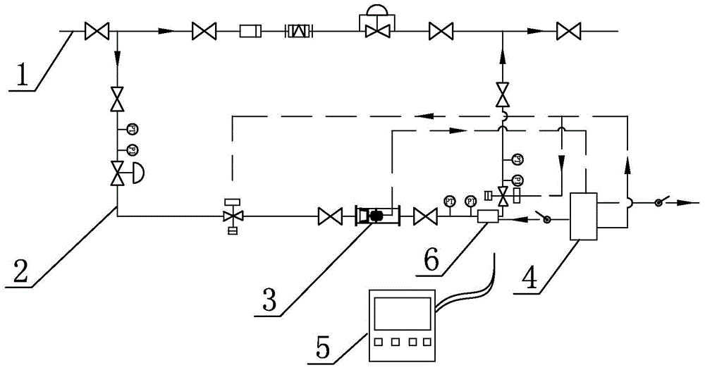
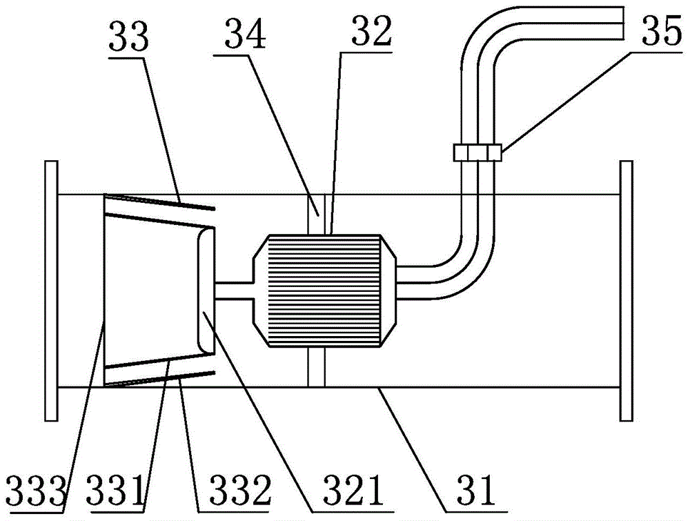
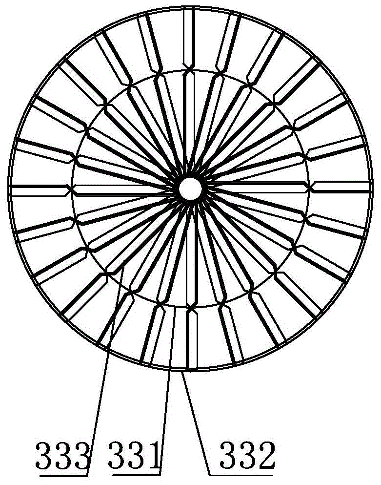
[0023] Such as Figure 1-2 As shown, the gas pipeline built-in power generation system in this embodiment uses the kinetic energy and pressure energy of the natural gas flowing in the main gas pipeline 1 to generate electricity, and provides electric energy to valves, instruments, monitoring, technical defense, etc. in remote areas or areas without power grids. The facility is used, specifically, the power generation system is located on the branch pipeline 2, the branch pipeline 2 is connected in parallel with the main gas pipeline 1, and the power generation device 3 is detachably installed on the branch pipeline 2, and the power generation device 3 includes a tubular casing 31 1. The generator 32 fixed in the casing 31 and the shroud 33 positioned at the power input end of the generator 32, the two ends of the section tubular casing 31 have connecting flanges, and the section tubular casing 31 is detachably installed on the On the branch pipeline 2, the generator 32 is fixe...


PUM


Abstract

The invention relates to an internal electricity generation system for a gas pipeline. The internal electricity generation system comprises a branch pipeline connected with a main gas delivery pipeline, an electricity generation device detachably arranged on the branch pipeline, and a power output device connected with the power output end of the electricity generation device. The electricity generation device comprises a sectional tube type housing, an electric generator fixed in the housing and a flow guide hood arranged at the power input end of the electric generator. The flow guide hood is composed of an inner hood body and an outer hood body and is of a double-layered gathering type flow guide structure. A hollow-out baffle plate is arranged on the end face of an inlet of the flow guide hood and comprises multiple baffle plate sheets in central symmetry. Each baffle plate sheet is provided with two opposite inclined planes which are located in the inner hood body and the space between the inner hood body and the outer hood body respectively. By means of the flow guide hood of the internal electricity generation system for the gas pipeline, a fluid channel can be made smaller, pressure is increased, and kinetic energy recovery efficiency is improved.

Description

technical field [0001] The invention relates to a power generation device, in particular to a system and an automatic control method for generating power by using kinetic energy in a gas pipeline. Background technique [0002] At present, in the process of gas pipeline transportation, since the monitoring and control devices are located in remote areas and far away from the power grid, this will cause power shortage or no power supply for monitoring and testing equipment, and there are hidden dangers. For example, there are many pressure adjustments in the process of natural gas transmission. The station is in a state of power shortage or no power supply due to its remote location, resulting in difficulty in power supply. Due to the remote location of these voltage regulating stations / boxes, it often occurs due to the lack of supply of mains power supply cables, and the necessary lighting and heating in winter. At the same time, because there is no external power supply, the...

Claims


Application Information

Patent Timeline
Patent Type & Authority Applications(China)
IPC IPC(8): F01D15/10F01D25/24F01D25/10H02J7/14F17D1/02
Inventor 李清张辉车子萍钱迪高岷徐文东朱军龙腾飞张荣伟
Owner BEIJING GAS GRP
Why Eureka
Try Eureka