Thermal defect infrared tracking and detecting device used for transformer substation

A tracking detection and substation technology, applied in the measurement of electricity, measurement devices, measurement of electrical variables, etc., can solve the problems affecting the overall operation of the power system, and achieve the effect of reliable design principle, prominent substantive features, and simple structure

Inactive Publication Date: 2015-10-28
STATE GRID CORP OF CHINA +1
View PDF8 Cites 3 Cited by
  • Summary
  • Abstract
  • Description
  • Claims
  • Application Information

AI Technical Summary

Problems solved by technology

[0003] In the prior art, when overhauling substation equipment, it is necessary to stop the power equipment and manually overhaul the substation; this kind of overhaul not only affects the overall operation of the power system, but also has certain risks

Method used


Image

  • Thermal defect infrared tracking and detecting device used for transformer substation
  • Thermal defect infrared tracking and detecting device used for transformer substation
  • Thermal defect infrared tracking and detecting device used for transformer substation

Examples


Embodiment 1

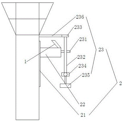
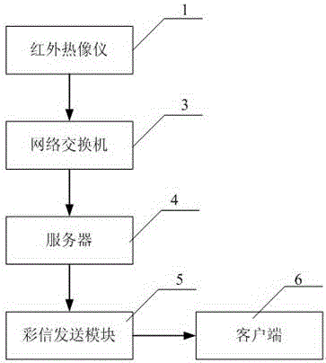
[0028] like Figures 1 to 3 As shown, a thermal defect infrared tracking detection device for a substation provided by the present invention includes an infrared thermal imager 1, and the infrared thermal imager 1 is fixed on the substation through a pan stand 2;

[0029] The thermal defect infrared tracking and monitoring equipment also includes a network switch 3 connected to the infrared camera 1, a server 4 connected to the network switch 3, a multimedia message sending module 5 connected to the server 4, and a multimedia message sending module 5 through Wi-Fi Client 6,

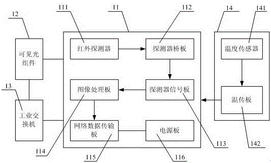
[0030] The infrared camera 1 includes an infrared core assembly 11, a visible light assembly 12, an industrial switch 13, and an external temperature collection assembly 14,

[0031] The infrared movement assembly 11 includes an infrared detector 111, a detector bridge plate 112 connected to the infrared detector 111, a detector signal board 113 connected to the detector bridge board 112, and a detector ...

Embodiment 2

[0043] The difference between this embodiment and Embodiment 1 is:

[0044] In this embodiment, the inclination angle between the thermal imaging camera 1 and the horizontal plane is 30 degrees; setting the inclination angle to 30 degrees can effectively collect infrared data of the substation.

Embodiment 3

[0046] The difference between this embodiment and Embodiment 1 is:

[0047] In this embodiment, the inclination angle between the thermal imaging camera 1 and the horizontal plane is 60 degrees; setting the inclination angle to 60 degrees can effectively collect infrared data of the substation.


PUM


Abstract

The present invention relates to a thermal defect infrared tracking and detecting device used for a transformer substation. The thermal defect infrared tracking and detecting device used for the transformer substation comprises an infrared thermal imager fixed on the transformer substation via a pan-tilt rack, and also comprises a network switch, a server, a multimedia message sending module and a client connected with the multimedia message sending module via a wireless network. The infrared thermal imager comprises an infrared movement assembly, a visible light assembly, an industrial switch and an external temperature acquisition assembly, and the infrared movement assembly comprises an infrared detector, a detector bridge board connected with the infrared detector, a detector signal board connected with the detector bridge board, an image processing board connected with the detector signal board, a network data transmission board connected with the image processing board, and a power supply board connected with the network data transmission board. The external temperature acquisition assembly comprises a temperature sensor and a temperature transmission board connected with the temperature sensor, the temperature transmission board is electrically connected with the detector signal board, and the visible light assembly and the industrial switch assembly are connected with the infrared movement assembly separately.

Description

technical field [0001] The invention belongs to the technical field of electric equipment detection, and relates to a detection device for a substation, in particular to a thermal defect infrared tracking detection device for a substation. The thermal defect infrared tracking detection device adopts the principle of infrared temperature measurement to collect infrared Data to judge the damage of electrical equipment, the operation is convenient and effective. Background technique [0002] With the construction of power safety production risk management system and the vigorous promotion of "condition-based maintenance" of substation equipment, real-time, effective and dynamic evaluation of the health status of power equipment has become a necessary condition to ensure the safety and stability of equipment during operation. [0003] In the prior art, when the substation equipment is overhauled, it is necessary to stop the power equipment and manually overhaul the substation; t...

Claims


Application Information

Patent Timeline
IPC IPC(8): G01R31/00G08C17/02
Inventor 耿晓刚马风刚赵亮张力郭连征王立华唐晓坤
Owner STATE GRID CORP OF CHINA
Why Eureka
Try Eureka