
Switching power supply control chip and flyback AC-DC converter

A technology for controlling chips and switching power supplies, applied in control/regulation systems, output power conversion devices, instruments, etc., can solve the problems of limited output power, high initial value of primary inductor current signal, etc., and achieve the effect of increasing output power

Active Publication Date: 2015-10-28
SHENZHEN WINSEMI MICROELECTRONICS
View PDF6 Cites 11 Cited by
  • Summary
  • Abstract
  • Description
  • Claims
  • Application Information

AI Technical Summary

Problems solved by technology

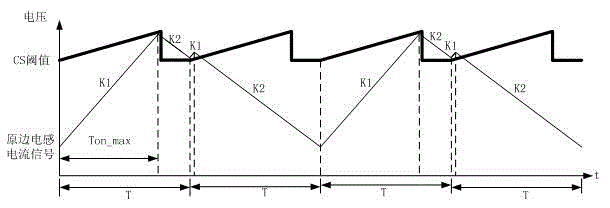
Since the discharge time of the large wave is very short (the time corresponding to K2 in the first cycle T), the initial value of the primary inductor current signal of the wavelet is very high, basically when it is turned on, it will hit the CS threshold, and the switch tube Q will be turned off immediately. The overall effect is equivalent to turning on once in two cycles, and the turn-on time is only the maximum on-time Ton_max, thus limiting the output power

Method used


Image

  • Switching power supply control chip and flyback AC-DC converter
  • Switching power supply control chip and flyback AC-DC converter
  • Switching power supply control chip and flyback AC-DC converter

Examples


Embodiment Construction

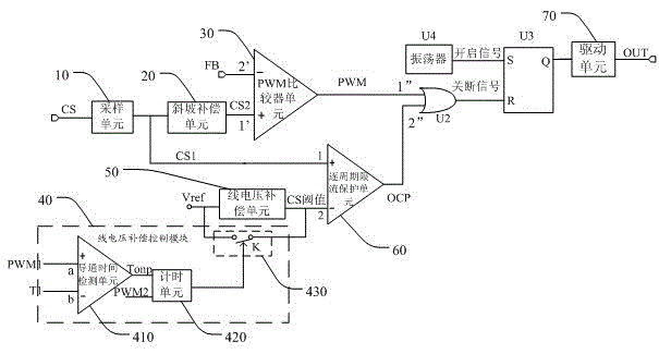
[0024] The invention provides a switching power supply control chip and a flyback AC-DC converter, which detects the conduction time of an external power MOS transistor through a line voltage compensation control module to determine whether to perform line voltage compensation on the primary inductor current in the next cycle, Prevent the output overcurrent point and recovery point from increasing with the increase of the line voltage under low voltage, and increase the output power.

[0025] In order to make the object, technical solution and effect of the present invention more clear and definite, the present invention will be further described in detail below with reference to the accompanying drawings and examples. It should be understood that the specific embodiments described here are only used to explain the present invention, not to limit the present invention.

[0026] see image 3 The switching power supply control chip provided by the present invention includes a s...


PUM


Abstract

The present invention discloses a switching power supply control chip and a flyback AC-DC converter. The switching power supply control chip comprises a sampling unit, a slope compensation unit, a PWM comparator unit, a line voltage compensation control module, a line voltage compensation unit, a cycle-by-cycle current-limiting protection unit, an or gate, an RS trigger, an oscillator and a driving unit. The switching power supply control chip provided by the present invention detects the conduction time of an external power MOS transistor by the line voltage compensation control module, when the conduction time is greater than the first preset time, within the conduction time of the next external power MOS transistor, controls the line voltage compensation unit not to carry out the line voltage compensation on a reference voltage within the second preset time, thereby preventing the situation that an output overcurrent point and a recovery point under a low voltage are not increased along with the increase of the line voltage, enabling the conduction time of the external power MOS transistors to be longer in each cycle, and improving the output power.

Description

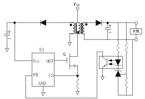
technical field [0001] The invention relates to the technical field of switching power supplies, in particular to a switching power supply control chip and a flyback AC-DC converter. Background technique [0002] figure 1 is a circuit diagram of a conventional flyback AC-DC converter. When the load output does not reach the over-current point, the shutdown signal of the OUT terminal of the control chip U1 is controlled by the feedback voltage (input from the FB terminal) and the primary current detection signal (input from the CS terminal). When the output load is very large and reaches the overcurrent point, the voltage of the FB terminal of the control chip U1 becomes very high. At this time, the shutdown signal output by the OUT terminal of the control chip U1 is determined by the peak value of the primary inductor current. Since the drive signal output by the OUT terminal of the control chip U1 has a certain turn-off delay Tdelay, under different input voltages Vin, th...

Claims


Application Information

Patent Timeline
Patent Type & Authority Applications(China)
IPC IPC(8): H02M3/156H02M7/217
Inventor 宋利军许煌樟
Owner SHENZHEN WINSEMI MICROELECTRONICS
Learn More