Magnetic resonance imaging apparatus

A technology of magnetic resonance imaging and magnetic resonance signals, applied in magnetic resonance measurement, measuring devices, measuring magnetic variables, etc.

Inactive Publication Date: 2015-10-28
KYOTO UNIV +1
View PDF5 Cites 1 Cited by
  • Summary
  • Abstract
  • Description
  • Claims
  • Application Information

AI Technical Summary

Problems solved by technology

The image generation unit uses magneti

Method used


Image

  • Magnetic resonance imaging apparatus
  • Magnetic resonance imaging apparatus
  • Magnetic resonance imaging apparatus

Examples


no. 1 Embodiment approach

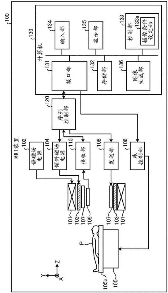
[0033] figure 1 It is a functional block diagram showing the configuration of the MRI apparatus 100 according to the first embodiment. Such as figure 1 As shown, the MRI apparatus 100 includes a static field magnet 101, a static field power supply 102, a gradient magnetic field coil 103, a gradient magnetic field power supply 104, a bed 105, a bed control unit 106, a transmitting coil 107, a transmitting unit 108, a receiving coil 109, and a receiving unit 110. , the sequence control unit 120, and the computer 130. In addition, the subject P (for example, a human body) is not included in the MRI apparatus 100 . in addition, figure 1 The shown structure is just an example. For example, each part in the sequence control part 120 and the computer 130 can also be comprised suitably integrated or separated.

[0034] The static field magnet 101 is a hollow cylindrical magnet, and generates a static magnetic field in the internal space. The static field magnet 101 is, for examp...

no. 2 Embodiment approach

[0090]Next, a second embodiment will be described. In the second embodiment, an example of imaging for obtaining a "uterine blood vessel image" will be described. In addition, the MRI apparatus 100 according to the second embodiment has the same configuration as that of the MRI apparatus 100 according to the first embodiment, and executes the same processing procedures as those in the first embodiment. Hereinafter, the description will focus on points different from the first embodiment.

[0091] Figure 13 It is a diagram for explaining the setting of the marker area and the imaging area in the second embodiment. In the second embodiment, it is desirable that the object of interest drawn in the image is "blood in the womb". Therefore, the operator sets the imaging region on the positioning image so as to include the "uterus" as the region of interest.

[0092] Additionally, if Figure 13 Shown, blood inflow from aorta in the uterus. Therefore, the operator sets a marked...

no. 3 Embodiment approach

[0109] Next, a third embodiment will be described. In the first and second embodiments described above, an example in which fixed values ​​are used as the first TI time and the second TI time has been described, but the embodiment is not limited thereto. Hereinafter, a method of setting a different 1st TI time according to each person's TR, and a method of obtaining the 1st TI time or the 2nd TI time by preparing a scan will be described. In addition, the method described below can be appropriately combined with the above-mentioned first and second embodiments or other embodiments.

[0110] (How to set different 1st TI time depending on TR)

[0111] First, a method of setting a different 1st TI time according to each individual's TR will be described. For example, in the first embodiment, it is assumed that "respiration-synchronized imaging" that performs imaging while synchronizing with the respiration of the subject P is applied. In respiratory-synchronous imaging, the re...


PUM


Abstract

A magnetic resonance imaging apparatus (100) according to one embodiment of the present invention is provided with a sequence control unit (120) and an image generation unit (136). The sequence control unit (120) collects magnetic resonance signals within an imaging region from the time a radio frequency (RF) pulse is applied to a labeling region until a prescribed amount of time has elapsed. The image generation unit (136) generates an image using the magnetic resonance signals. Also, the sequence control unit (120) sets the application timing of the RF pulse such that a first amount of time, from the time when the first RF pulse is applied without selecting a region until the collection of the magnetic resonance signals starts, differs from a second amount of time, from the time when the labeling region is selected and the second RF pulse is applied until the collection of magnetic resonance signals starts.

Description

technical field [0001] Embodiments of the present invention relate to a magnetic resonance imaging apparatus. Background technique [0002] Magnetic resonance imaging magnetically excites the nuclear spins of the subject placed in a static magnetic field by RF (Radio Frequency: radio frequency) pulses of Larmor frequency. An imaging method that generates images from resonance signal data. [0003] As one of magnetic resonance imaging, MRA (Magnetic Resonance Angiography: Magnetic Resonance Angiography) has attracted attention. In non-contrast MRA that performs imaging without administering a contrast agent, for example, a labeling pulse is applied to blood in a labeling area set upstream of a blood vessel, and after a predetermined time elapses, data on the area of ​​interest is collected to selectively Delineate blood flow to the area of ​​interest. However, in this non-contrast MRA, it may be difficult to obtain a sufficient image in view of the drawing of peripheral bl...

Claims


Application Information

Patent Timeline
IPC IPC(8): A61B5/055
CPCA61B5/055G01R33/5602G01R33/5607G01R33/5613G01R33/56333G01R33/5673G01R33/5635A61B5/704A61B5/0055A61B5/4244A61B5/4325G01R33/36G01R33/543
Inventor 矶田裕义藤本晃司草原博志
Owner KYOTO UNIV
Why Eureka
Try Eureka