Automatic punch device of mold push rod

A technology of automatic punching and punching devices, applied in the direction of feeding devices, positioning devices, storage devices, etc., can solve the problems of ineffective use of waste heat of electromagnetic induction coils, ineffective use of energy, and a large amount of manual input. , to achieve the effect of improving energy utilization, shortening processing cycle and reducing energy consumption

Inactive Publication Date: 2015-11-04
安徽省振华科技工业有限公司
View PDF5 Cites 6 Cited by
  • Summary
  • Abstract
  • Description
  • Claims
  • Application Information

AI Technical Summary

Problems solved by technology

[0002] In the process of processing the existing push rods for molds, the head of the push rod is formed by stamping. At present, the equipment used in the processing plant is a single processing type, that is, one device can only realize one at a time. The molding of the push rod head requires one employee to operate each piece of equipment. Manual loading and unloading is required, and the degree of automation is low. For orders with a large processing volume, a large amount of manual input is required, and the efficiency is low; electromagnetic induction Heating is a relatively common heating method. It is used in the stamping process of push rods. Since it is a single processing type, after each heating is completed, the electromagnetic induction coil is removed, and the stamping and manual unloading are performed. This replacement cycle is relatively short. Long, the waste heat of the electromagnetic induction coil itself cannot be effectively utilized. Along with the unloading process, the electromagnetic induction coil will gradually cool down. less than effective use

Method used


Image

  • Automatic punch device of mold push rod
  • Automatic punch device of mold push rod
  • Automatic punch device of mold push rod

Examples


Embodiment Construction

[0023] In order to make the technical means, creative features, goals and effects achieved by the present invention easy to understand, the present invention will be further elaborated below.

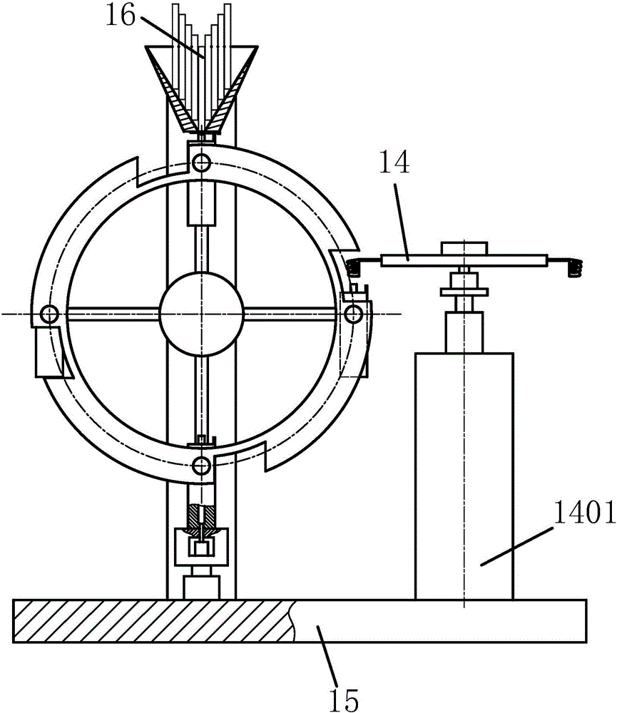
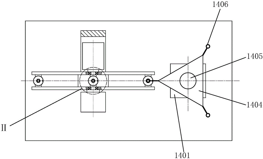
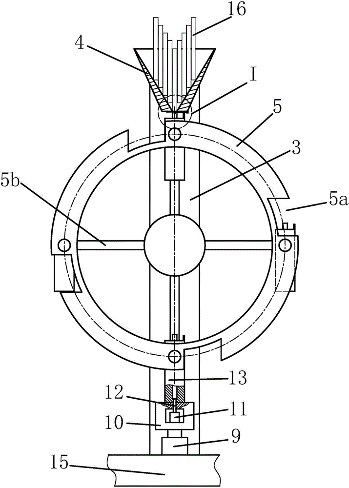
[0024] Such as Figure 1 to Figure 8 As shown, an automatic punching device for a mold push rod, including a base plate 15, a rotary heater 14, a machine table 1, a main drive motor 2, a vertical beam 3, a funnel-shaped storage box 4, and a circular feeder device, pad supporting device and punching device, the machine table 1 is installed on the left part of the upper end surface of the base plate 15, the rotary heater 14 is installed on the right part of the upper end face of the base plate 15, and the main drive motor 2 is horizontally fixed on the In the middle part of the upper end of the machine platform 1, the vertical suspension beam 3 is vertically installed on the upper end surface of the machine platform 1, the funnel-shaped material storage box 4 is fixed on the upper end of ...


PUM


Abstract

The invention relates to an automatic punch device of a mold push rod. The device comprises a basal plate, a revolving heater, a stand, a main driving motor, a vertical lifting beam, a funnel type storage tank, a circular taking suppler, a support pad device and a punching device, wherein the stand is mounted at the left part of the upper end surface of the basal plate; the revolving heater is mounted at the right part of the upper end surface of the basal plate; the main driving motor is horizontally fixed in middle of the upper end of the stand; the vertical lifting beam is vertically mounted on the upper end surface of the stand; the funnel type storage tank is fixed at the upper end of the vertical lifting beam; the circular taking suppler is mounted on the main driving motor; the support pad device is connected with the basal plate; and the punching device is fixed on the basal plate. The device has such advantages as reasonable structure design, high automation degree and short production period, can realize the batch punch machining of the push rod, replaces the traditional manual operation, greatly improves the production efficiency, reduces the labor cost, shortens the machining period of the push rod, and improves the energy utilization rate.

Description

technical field [0001] The invention relates to the technical field of mold accessories processing, in particular to an automatic punch device for a mold push rod. Background technique [0002] In the process of processing the existing push rods for molds, the head of the push rod is formed by stamping. At present, the equipment used in the processing plant is a single processing type, that is, one device can only realize one at a time. The molding of the push rod head requires one employee to operate each piece of equipment. Manual loading and unloading is required, and the degree of automation is low. For orders with a large processing volume, a large amount of manual input is required, and the efficiency is low; electromagnetic induction Heating is a relatively common heating method. It is used in the stamping process of push rods. Since it is a single processing type, after each heating is completed, the electromagnetic induction coil is removed, and the stamping and man...

Claims


Application Information

Patent Timeline
IPC IPC(8): B21D22/02B21D43/14B21D45/08B21D37/16
Inventor 汪家武
Owner 安徽省振华科技工业有限公司
Why Eureka
Try Eureka