Laser edge scanning device capable of machining glass chip of any shape

A glass chip and arbitrary shape technology, which is applied in laser welding equipment, metal processing equipment, manufacturing tools, etc., can solve the problems of affecting the processing quality, poor edge sweeping accuracy, and inability to accurately control the edge sweeping parallelism, achieving improved accuracy, Strong flexibility and variability, improved edge sweeping accuracy

Active Publication Date: 2015-11-04
HANERGY MOBILE ENERGY HLDG GRP CO LTD
View PDF5 Cites 5 Cited by
  • Summary
  • Abstract
  • Description
  • Claims
  • Application Information

AI Technical Summary

Problems solved by technology

[0003] In order to solve the problem that the parallelism of edge sweeping cannot be precisely controlled in the process of edge sweeping of glass chips by laser, which leads to poor edge sweep accuracy and affects the processing quality, the present invention further proposes a laser sweeper capable of processing glass chips of any shape. side device

Method used


Image

  • Laser edge scanning device capable of machining glass chip of any shape
  • Laser edge scanning device capable of machining glass chip of any shape

Examples


specific Embodiment approach 1

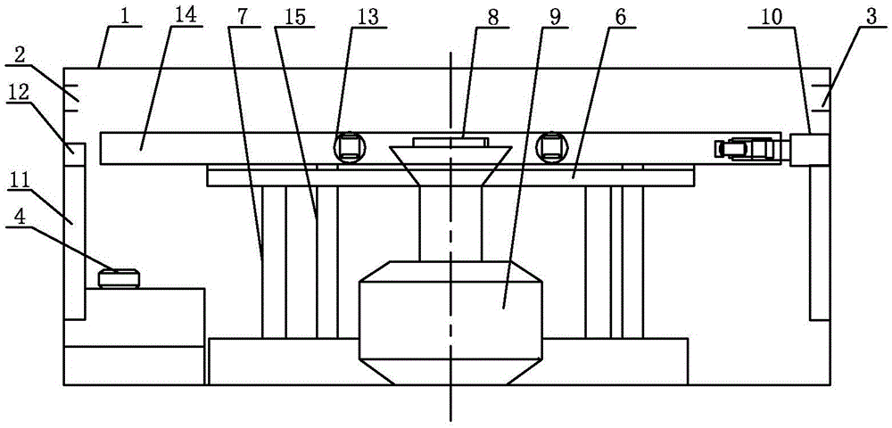
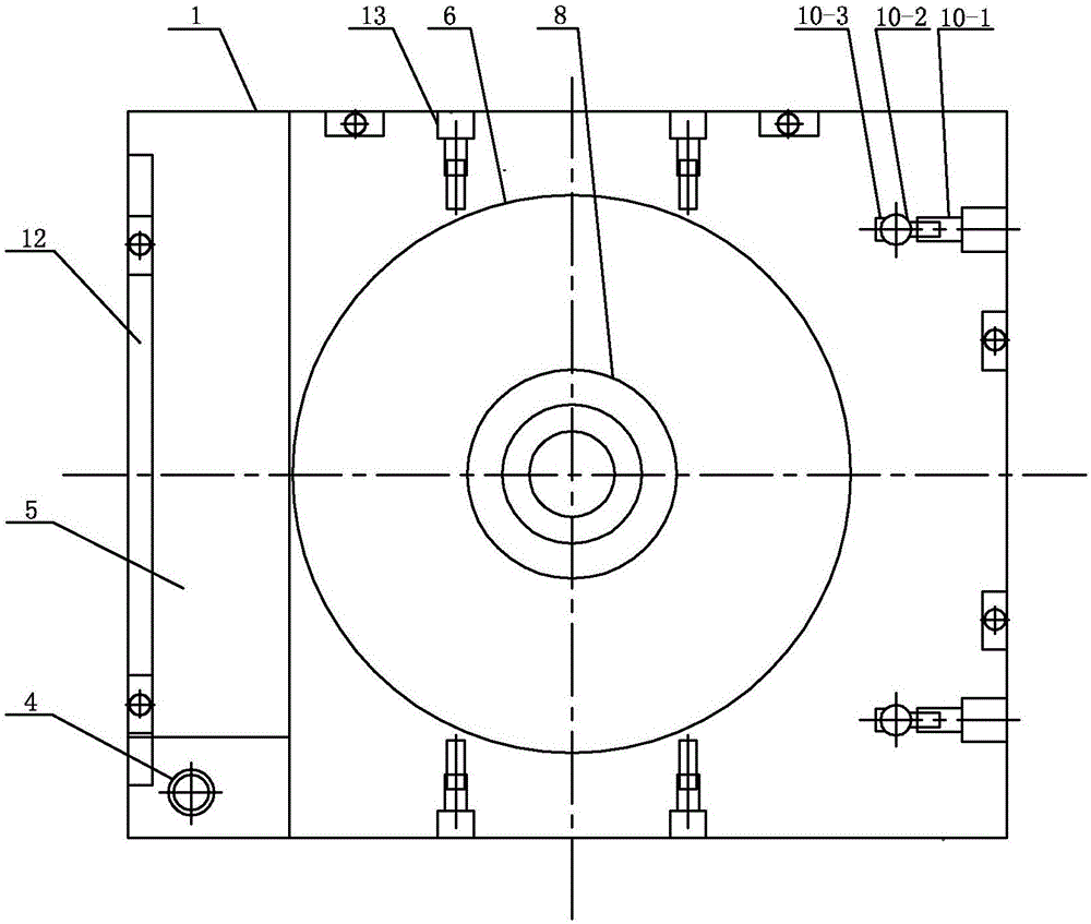
[0013] Specific implementation mode one: combine figure 1 and figure 2 Describe this embodiment mode, a laser edge sweeping device that can process glass chips of any shape described in this embodiment mode, it includes a housing 1, a laser 4, a laser track 5, an air floating platform 6 and at least one pillar 7, the housing 1 is Rectangular box body, the air floating platform 6 is arranged in the middle of the shell 1 through at least one pillar 7, the left side wall of the shell 1 is provided with a feed port 2, and the right side wall of the shell 1 is provided with a discharge port 3, The feed port 2 is set opposite to the discharge port 3, and the laser 4 is set in the laser track 5. A laser edge sweeping device capable of processing glass chips of any shape also includes a vacuum chuck 8, a rotatable support 9, a positioning device, two Universal pusher 10 and two liftable brackets 11, the air bearing platform 6 is circular, the vacuum suction cup 8 is arranged in the ...

specific Embodiment approach 2

[0015] Specific implementation mode two: combination figure 1 and figure 2 Describe this embodiment, the positioning device described in this embodiment includes a clip guide rail 14, at least one clip guide rail support column 15 and a plurality of clips 13, the clip guide rail 14 is arranged above the air bearing platform 6, and at least one clip guide rail support column 15 The upper end is evenly arranged on the lower surface of the clip guide rail 14, the lower end of at least one clip guide rail support column 15 is evenly arranged on the upper surface of the bottom end surface of the housing 1, and a plurality of clips 13 are movably arranged in the clip guide rail 14. With such arrangement, the clamp 13 can move telescopically to position glass chips at different angles and then clamp them. Other compositions and connections are the same as those in the first embodiment.

specific Embodiment approach 3

[0016] Specific implementation mode three: combination figure 2 To describe this embodiment, the number of clips 13 in this embodiment is four. In this way, the glass chip is quadrilateral, and the four clips 13 respectively fix the four sides of the glass chip, so that the positioning of the glass chip is more precise and firm. Other compositions and connections are the same as those in the second embodiment.


PUM


Abstract

The invention provides a laser edge scanning device capable of machining a glass chip of any shape, and relates to the field of solar cell module machining. The laser edge scanning device aims at solving the problems that due to the fact that in a traditional process for conducting edge scanning on the glass chip through lasers, the edge scanning parallelism can not be accurately controlled, the edge scanning accuracy is poor and the machining quality is influenced. According to the laser edge scanning device capable of machining the glass chip of any shape, an air-floating platform is in an annular shape; a vacuum suction cup is arranged in the middle in a shell; the lower end of the vacuum suction cup is arranged on the upper surface of the bottom end face of the shell through a rotatable support; the upper end of the vacuum suction cup penetrates out of a central hole of the air-floating platform; a positioning device is arranged above the air-floating platform; two universal push handles are fixedly connected with the upper end of an adjustable support which is arranged on the right side wall of the shell; the length direction of each universal push handle is perpendicular to the length direction of the adjustable support; and the two universal push handles are symmetrical about the central line, in the length direction, of the shell. The laser edge scanning device is used for machining the glass chip.

Description

technical field [0001] The invention relates to a laser edge sweeping device, in particular to a laser edge sweeping device capable of processing glass chips with arbitrary shapes. Background technique [0002] As an important component of solar panels, glass chips need to be edge-swept before use. Laser edge-sweeping has become an important process for all thin-film solar cell processing due to its advantages of high energy and fast speed. The design of traditional laser edge sweeping is that the laser only moves in a straight line. After the glass chip enters the machine, it is positioned by the positioning cylinder. The laser moves down horizontally and emits light to sweep the short side of the front of the glass, and then the glass chip is clamped by the clip and moved to the front. , at this time the laser does not move, but the light emits light to sweep off the lower long side of the glass, then the glass chip is fixed, the laser moves upward horizontally to sweep of...

Claims


Application Information

Patent Timeline
Patent Type & Authority Applications(China)
IPC IPC(8): B23K26/00B23K26/08B23K26/70
CPCB23K26/0823B23K26/0869B23K26/3576
Inventor 季海蛟信德磊赵雷宋玉超
Owner HANERGY MOBILE ENERGY HLDG GRP CO LTD
Why Eureka
Try Eureka