Welding lap joint structure and method for thin-wall pipes

A technology for connecting structures and pipes, applied in electron beam welding equipment, welding equipment, welding equipment, etc., can solve problems such as structural limitations of welded parts, and achieve the effect of avoiding spatter and ensuring the quality of cross-section welds

Active Publication Date: 2015-11-04
AECC AVIATION POWER CO LTD
View PDF5 Cites 8 Cited by
  • Summary
  • Abstract
  • Description
  • Claims
  • Application Information

AI Technical Summary

Problems solved by technology

[0003] In order to solve the problems in the prior art, the present invention proposes a thin-walled pipe welding lap joint structure and method that can solve the problem of electron beam welding having structural restrictions on welded parts

Method used


Image

  • Welding lap joint structure and method for thin-wall pipes
  • Welding lap joint structure and method for thin-wall pipes

Examples


Embodiment Construction

[0022] The present invention will be further explained below in combination with specific embodiments and accompanying drawings.

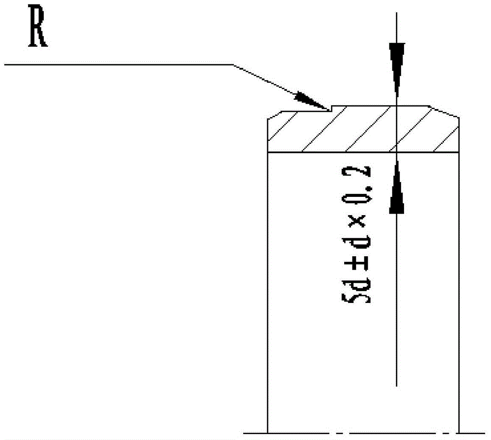
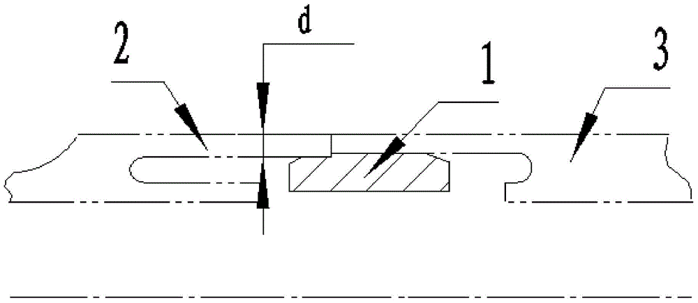
[0023] see figure 1 with figure 2 , a thin-walled pipe welded lap joint structure, including a supporting lining ring 1 of the same material as the pipe to be welded, the supporting lining ring 1 adopts a two-stage stepped structure, and a small end and a large end of the supporting lining ring 1 are formed The step of R≤0.1mm is excessive, the axial length of the small end of the support ring 1 is 3-5mm, and the axial length of the large end is 8-12mm, and the edges of the small end and the large end of the support ring 1 are provided with chamfers . The small end of the supporting backing ring 1 is assembled with the overlapping part of the welded short pipe 2, the large end of the supporting backing ring 1 is assembled with the overlapping part of the welding long pipe 3, and the small end and the large end of the supporting backing ring 1 ar...


PUM

PropertyMeasurementUnit
lengthaaaaaaaaaa
lengthaaaaaaaaaa

Abstract

The invention discloses a welding lap joint structure and method for thin-wall pipes. The welding lap joint structure and method aim at avoiding limitation of electron beam welding to the structures of welded parts. According to the technical scheme, the welding lap joint structure comprises a supporting bushing ring (1) made of the material the same as that of the welded pipes. The supporting bushing ring (1) is of a two-step-shaped structure. The lap joint portion of the short welded pipe (2) is assembled at the small end of the supporting bushing ring (1). The lap joint portion of the long welded pipe (3) is assembled at the large end of the supporting bushing ring (1). The lap joint portions of the short welded pipe (2) and the long welded pipe (3) are each of an orifice-shaped or groove-shaped structure. The supporting bushing ring (1) can be assembled in the orifice-shaped or groove-shaped structures. The lap joint portions of the short welded pipe (2) and the long welded pipe (3) are flush and end faces are in butt joint in the lap joint process of the supporting bushing ring (1).

Description

technical field [0001] The invention belongs to the field of mechanical processing, and in particular relates to a thin-wall pipe welding lap joint structure and method used in electron beam welding of butt ring welds of thin-wall pipe fittings. Background technique [0002] Before electron beam welding of butt girth welds of thin-walled pipe fittings, it is necessary to design welding joints to assemble and overlap each part, so as to meet the pre-weld assembly gap and reliable positioning of each part, and provide a basic guarantee for the quality of electron beam welding. According to the conventional design, the electron beam welding joint should be designed on one of the parts to be welded. However, due to the particularity of the structure of some parts, if the welded joint is designed on the part base, part of the profile of the part will not be able to be processed due to the interference of the welded joint. Contents of the invention [0003] In order to solve th...

Claims


Application Information

Patent Timeline
Patent Type & Authority Applications(China)
IPC IPC(8): B23K37/053B23K15/04B23K101/06
CPCB23K15/0006B23K15/0013B23K15/04B23K37/0533B23K2101/06
Inventor 李林燊阮成勇王继虎穆涛王雷雷王静娜
Owner AECC AVIATION POWER CO LTD
Why Eureka
Try Eureka