Spiral extrusion type solid-liquid separator and solid-liquid separating method
A solid-liquid separator and screw extrusion technology, applied in the direction of presses, manufacturing tools, etc., can solve the problems of high moisture content of solids, poor separation effect, poor applicability, etc., and achieve low suspended particle content and moisture content. Low, widely applicable effect
- Summary
- Abstract
- Description
- Claims
- Application Information
AI Technical Summary
Problems solved by technology
Method used
Image
Examples
Embodiment 1
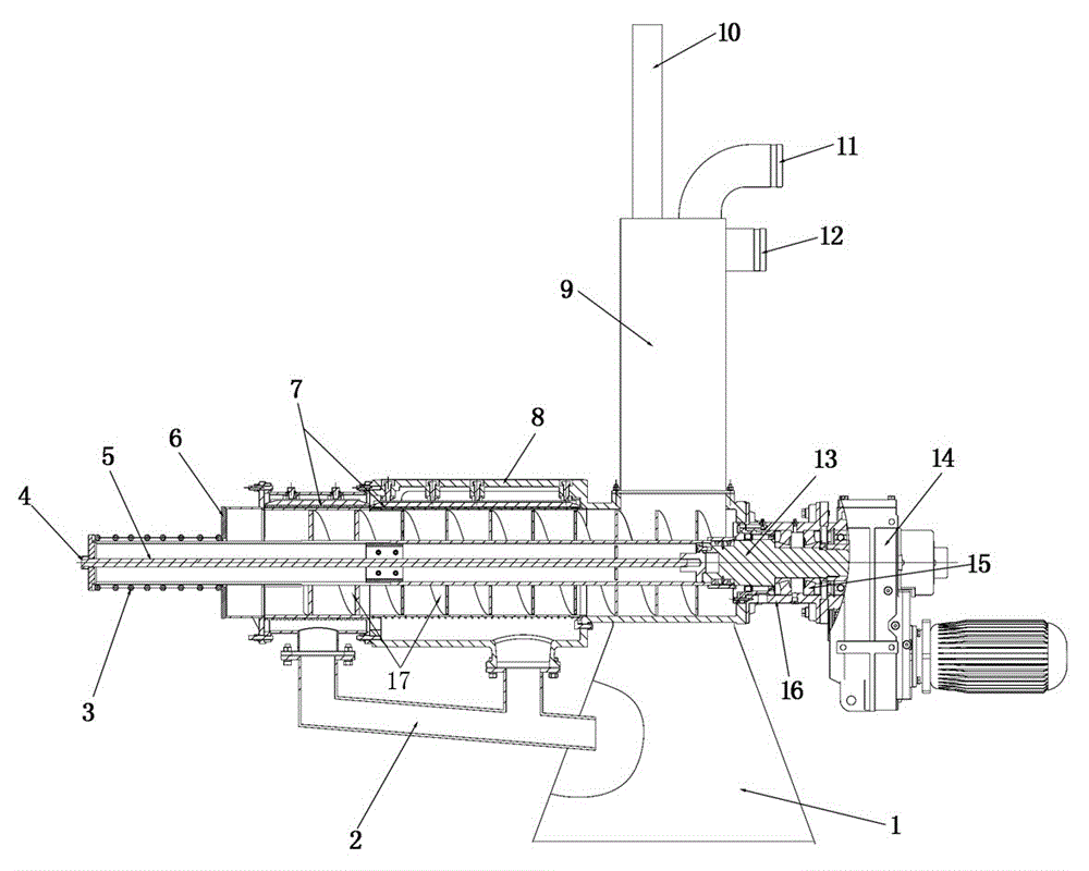
[0035] The equipment of the present invention consists of a feed mechanism, a power mechanism, a screw extrusion mechanism, a solid discharge mechanism, a liquid discharge mechanism and a base 1 (see figure 1 )constitute.
[0036] Such as figure 1 As shown, the feeding mechanism includes a buffer 9 arranged vertically, a feed inlet 11 arranged above the buffer 9 and an overflow outlet 12 arranged on the upper part of the side wall of the buffer 9 . An exhaust pipe 10 is also arranged on the buffer 9 .
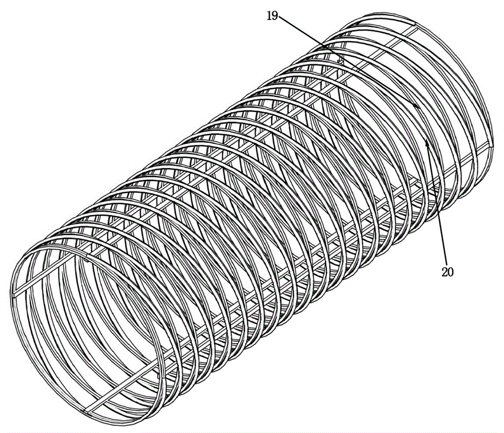
[0037] The lower end of the feeding mechanism is connected with the screw extruding mechanism. Such as figure 1 , The screw extrusion mechanism is composed of the main body sleeve 8, the filter screen cylinder 7 arranged in the main body sleeve 8 and the auger 5 arranged in the filter screen cylinder 7. Wherein, the specific structure of filter screen cylinder 7 and auger 5 is as follows:
[0038] ① Auger 5:
[0039] Such as figure 1 As shown, the auger 5 is made of an a...
Embodiment 2
[0049] Utilize the solid-liquid separator of embodiment 1 to carry out the method for solid-liquid separation:
[0050] Turn on the machine, the reduction motor 14 drives the auger 5 to rotate clockwise through the transmission main shaft 13, and then the material to be separated is sent into the buffer 9 through the feed port 11, and the material is transported backward under the action of the rotating auger 5, and is extruded at the same time. pressure. When the material passes through the auger 21 in the front section, the preliminary extrusion is completed, and the extruded water is filtered out through the filter screen cylinder in the front section, and then flows out through the liquid discharge mechanism; the remaining material remains in the screen cylinder 7 and is transported backward to the auger in the rear section. The dragon 22 is further extruded in the auger 22 of the rear section, and the remaining water is filtered out through the filter screen cylinder of t...
Embodiment 3
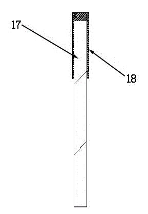
[0053] In order to further improve the durability of the screw blade 17 of this equipment, the structure of the front section auger screw blade 23 and the rear section auger screw blade 24 can be further improved on the basis of embodiment 1, and its structure is respectively as follows Figure 4 , Figure 5 shown. Such as Figure 4 As shown, the edge of the main structure of the front auger helical blade 23 is a "convex" cross-section, and the covered high wear-resistant rubber strip 18 has a groove that matches the cross-section, so that the entire surface of the helical blade formed in this way is smooth , not easy to fall off during work. The structure of rear section auger screw blade 24 is as Figure 5 As shown, its edge is a special-shaped "convex" cross-section, and the spiral blade formed in this way has higher strength, which meets the requirements of the rear auger for blade strength.
PUM
| Property | Measurement | Unit |
|---|---|---|
| Gap | aaaaa | aaaaa |
Abstract
Description
Claims
Application Information
 - R&D
- Intellectual Property
- Life Sciences
- Materials
- Tech Scout
- Unparalleled Data Quality
- Higher Quality Content
- 60% Fewer Hallucinations
Browse by: Latest US Patents, China's latest patents, Technical Efficacy Thesaurus, Application Domain, Technology Topic, Popular Technical Reports.
© 2025 PatSnap. All rights reserved.Legal|Privacy policy|Modern Slavery Act Transparency Statement|Sitemap|About US| Contact US: help@patsnap.com


