Quilting machine

A technology of quilting machines and needles, applied in the field of quilting machines, which can solve problems such as excessive stitch spacing, high energy consumption, and increased failure rate, and achieve the effects of uniform stitch spacing, stable travel system, and guaranteed product quality

Inactive Publication Date: 2015-11-04
NAIMAN BANNER GRASSLAND SHOW CASHMERE PROD
View PDF11 Cites 3 Cited by
  • Summary
  • Abstract
  • Description
  • Claims
  • Application Information

AI Technical Summary

Problems solved by technology

[0002] There are many problems in the existing quilting machine technology: 1. Using a single high-power drive motor, the cost of machine manufacturing is high, and the energy consumption is large, which is not conducive to reducing costs; the single-motor drive mode is likely to cause deformation of the machine itself and increase the failure rate ; 2. The needle beam is driven by the reducer to work along the guide rail, and the needle beam is easy to shake, causing problems such as stitch deviation, stitch overlapping, and excessive stitch spacing in the sewing process, resulting in defective products; 3. The existing technology mostly uses Single-row needles or double-row needle structures fixed on the same needle fixing beam. The general double-row needles are fixed on the same horizontal plane and adopt equal-length front and rear needle rows. The needle is easy to break and requires a large driving force; 4. The existing bottom thread passing system is easy to get stuck, resulting in too many coils and thread ends on the surface of the product, which affects the clean appearance; 5. The existing feeding system often has raw material accumulation. When starting the quilting machine again, it is necessary to clean up the twisted raw material cloth in the feeding system, which will not only easily cause waste of raw materials but also a lot of labor waste

Method used


Image

  • Quilting machine
  • Quilting machine
  • Quilting machine

Examples


Embodiment Construction

[0034] Specific embodiments of the present invention will be described below in conjunction with the accompanying drawings.

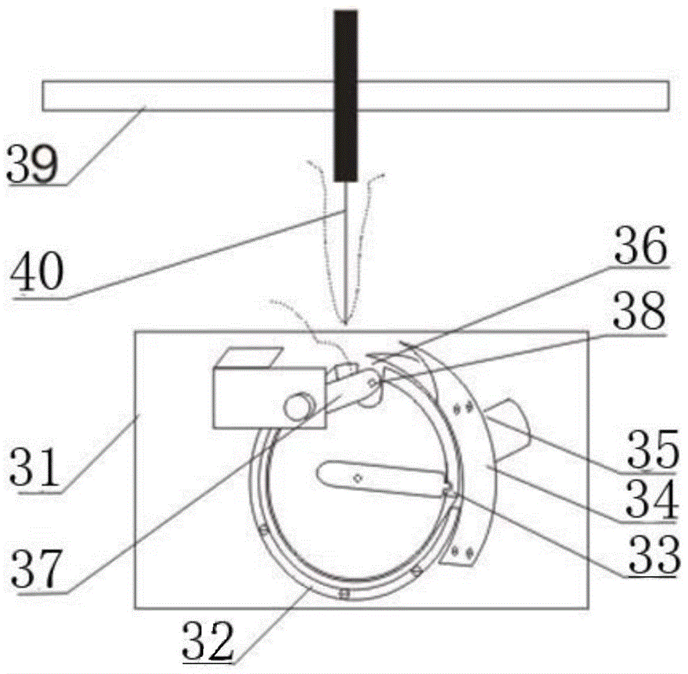
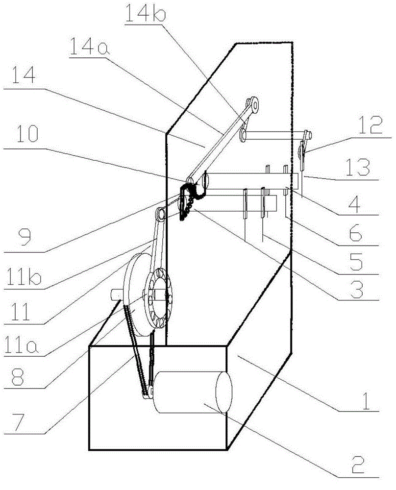
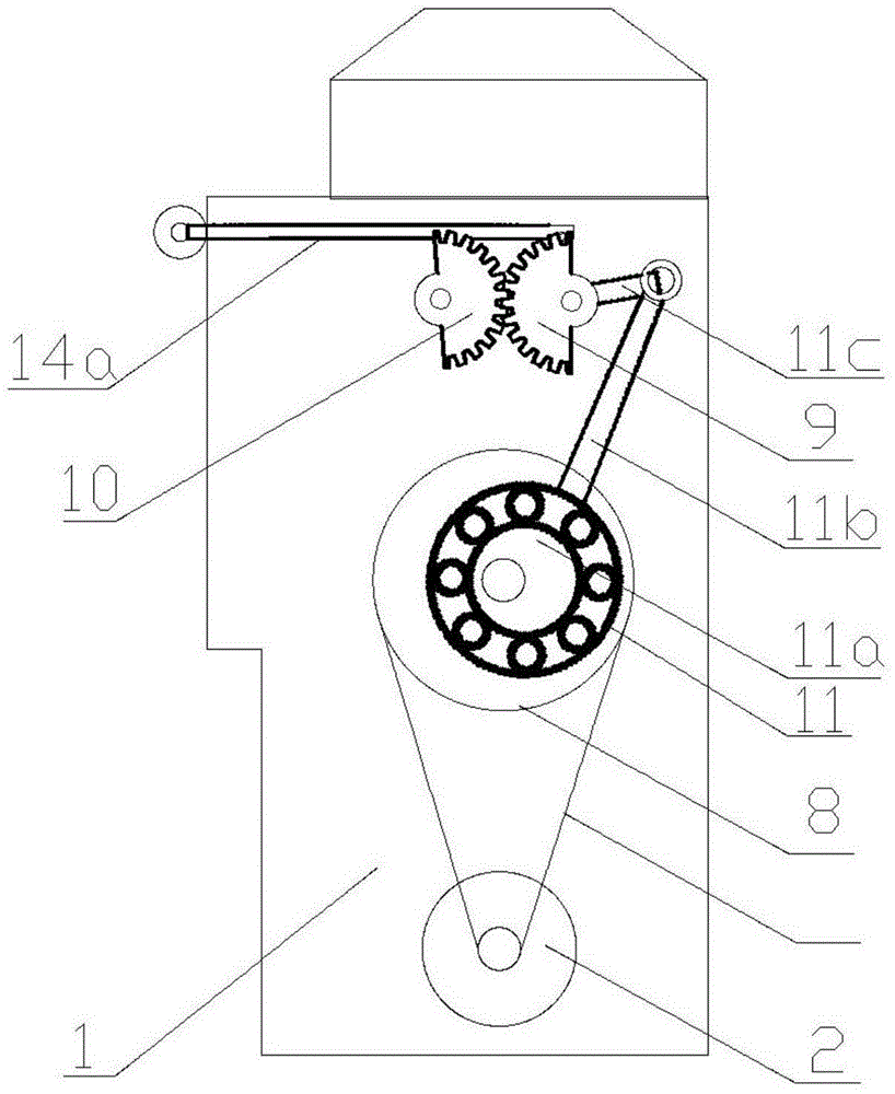
[0035] Such as figure 1 with 2 As shown, a quilting machine needle bar travel system, which includes a frame 1, on which the front needle installation crossbeam 3, the rear needle installation crossbeam 4, and the needle drive system can be slid up and down; A plurality of front row of needles 5 and a rear row of needles 6 are arranged on the front row of needle installation crossbeam 3 and the rear row of needle installation crossbeam 4 respectively.

[0036] The needle drive system includes a drive motor 2, a transmission wheel 8, and a front row needle transmission gear 9 and a rear needle transmission gear 10 that cooperate with each other; the drive motor 2 drives the transmission wheel 8 to rotate through a belt transmission structure 7 composed of a belt and a pulley , the transmission wheel 8 drives the front needle transmission gear 9 to swin...


PUM

PropertyMeasurementUnit
Lengthaaaaaaaaaa

Abstract

The invention discloses a quilting machine needle rod stroke system which comprises a rack. The rack is provided with a front-row-needle mounting beam capable of sliding up and down, a rear-row-needle mounting beam and a machine needle drive system. The machine needle drive system comprises a drive motor, a transmission wheel, a front-row-needle transmission gear and a rear-row-needle transmission gear, wherein the front-row-needle transmission gear and the rear-row-needle transmission gear are matched with each other. The drive motor drives the transmission wheel to rotate through a belt transmission structure. The transmission wheel drives the front-row-needle transmission gear and the rear-row-needle transmission gear to swing synchronously through a connection rod mechanism. The front-row-needle transmission gear drives the front-row-needle mounting beam to swing up and down through a front-row-needle transmission mechanism. The rear-row-needle transmission gear drives the rear-row-needle mounting beam to swing up and down through a rear-row-needle transmission mechanism. The machine needle rod stroke system is more steady, high in production efficiency and low in energy consumption.

Description

technical field [0001] The invention relates to the textile machinery industry, in particular to a quilting machine. Background technique [0002] There are many problems in the existing quilting machine technology: 1. Using a single high-power drive motor, the cost of machine manufacturing is high, and the energy consumption is large, which is not conducive to reducing costs; the single-motor drive mode is likely to cause deformation of the machine itself and increase the failure rate ; 2. The needle beam is driven by the reducer to work along the guide rail, and the needle beam is easy to shake, causing problems such as deviation of stitches, overlap of stitches, excessive stitch spacing, and defective products during the sewing process; 3. The existing technology mostly uses Single-row needle or double-row needle structure fixed on the same needle fixing crossbeam. Universal double-row needles are fixed on the same horizontal plane and front and rear rows of needles are o...

Claims


Application Information

Patent Timeline
IPC IPC(8): D05B11/00D05B33/00
Inventor 吕海利李世君
Owner NAIMAN BANNER GRASSLAND SHOW CASHMERE PROD
Why Eureka
Try Eureka