Inner-connection meshing type gear device

A gear device and gear technology, applied in the direction of gear transmission, transmission, transmission parts, etc., can solve the problems of inability to confirm the evaluation results of bearing monomers, inability to freely choose processing manufacturers, and affect product durability, etc., to achieve simple shape , Easy assembly and simplified internal accessories

Inactive Publication Date: 2015-11-04
亚杩拓精密机械(上海)有限公司
View PDF5 Cites 2 Cited by
  • Summary
  • Abstract
  • Description
  • Claims
  • Application Information

AI Technical Summary

Problems solved by technology

[0010] This structure can realize the miniaturization of the reducer, but on the other hand, the sliding parts of the bearing rolling elements of the housing 9 and the input side support body 5 and the output side support body 6 need high-precision grinding, resulting in difficult processing, and if the processing accuracy When lower, it will directly affect the durability of the product
Therefore, expensive processing equipment is required for processing related parts, and processing manufacturers that can perform high-precision processing are required to be able to produce, resulting in the inability to freely choose a processing manufacturer, which eventually leads to an increase in costs
[0011] In addition, due to the inability to confirm and use the evaluation results of the bearing unit provided by the bearing manufacturer, the performance test of the reducer itself can only be implemented after the reducer is completed.
In addition, the housing 9, the input-side support body 5, and the output-side support body 6 are dedicated parts with respect to the bearing 10 assembled thereon, and even if the load on the reducer changes, the bearing cannot be changed.

Method used


Image

  • Inner-connection meshing type gear device
  • Inner-connection meshing type gear device
  • Inner-connection meshing type gear device

Examples


Embodiment Construction

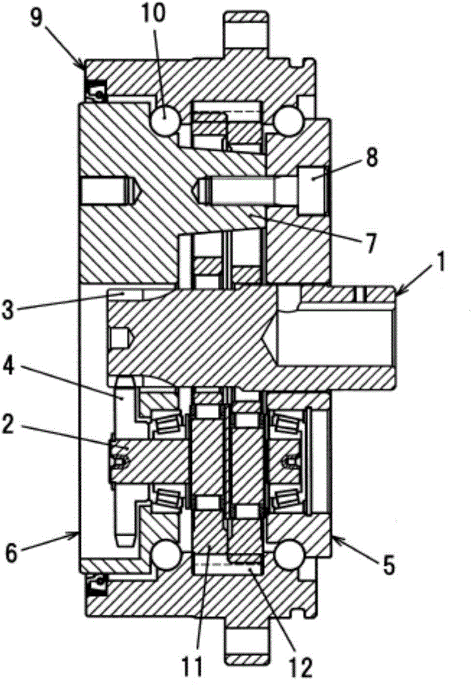
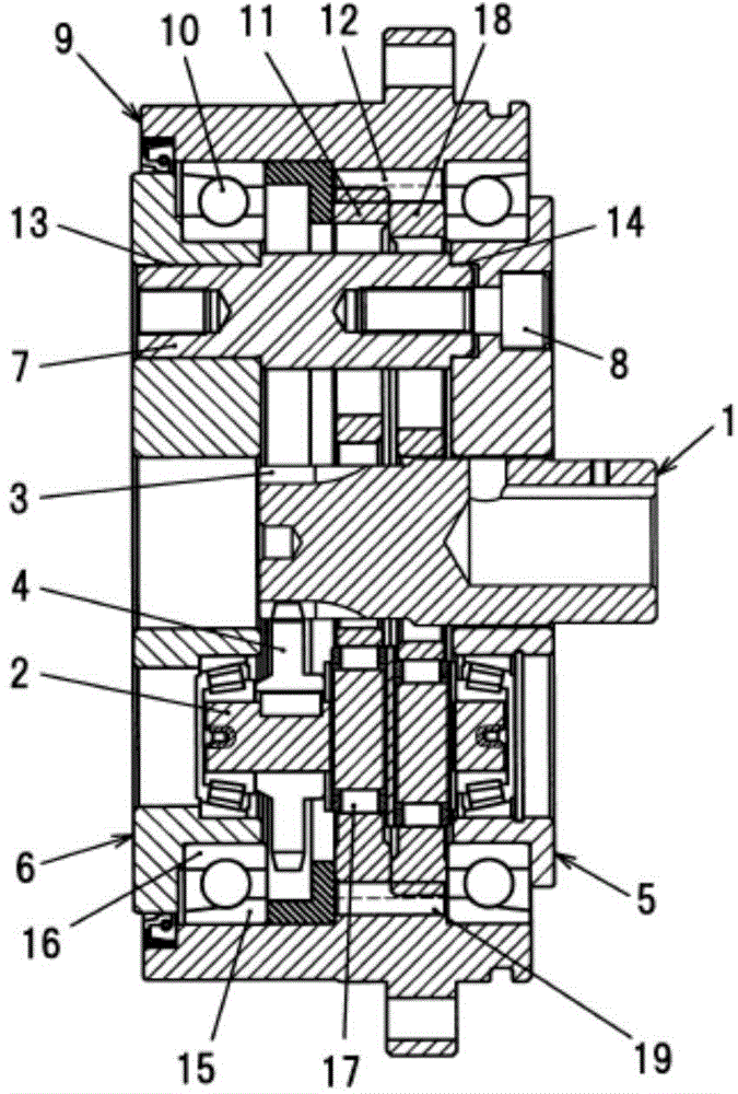
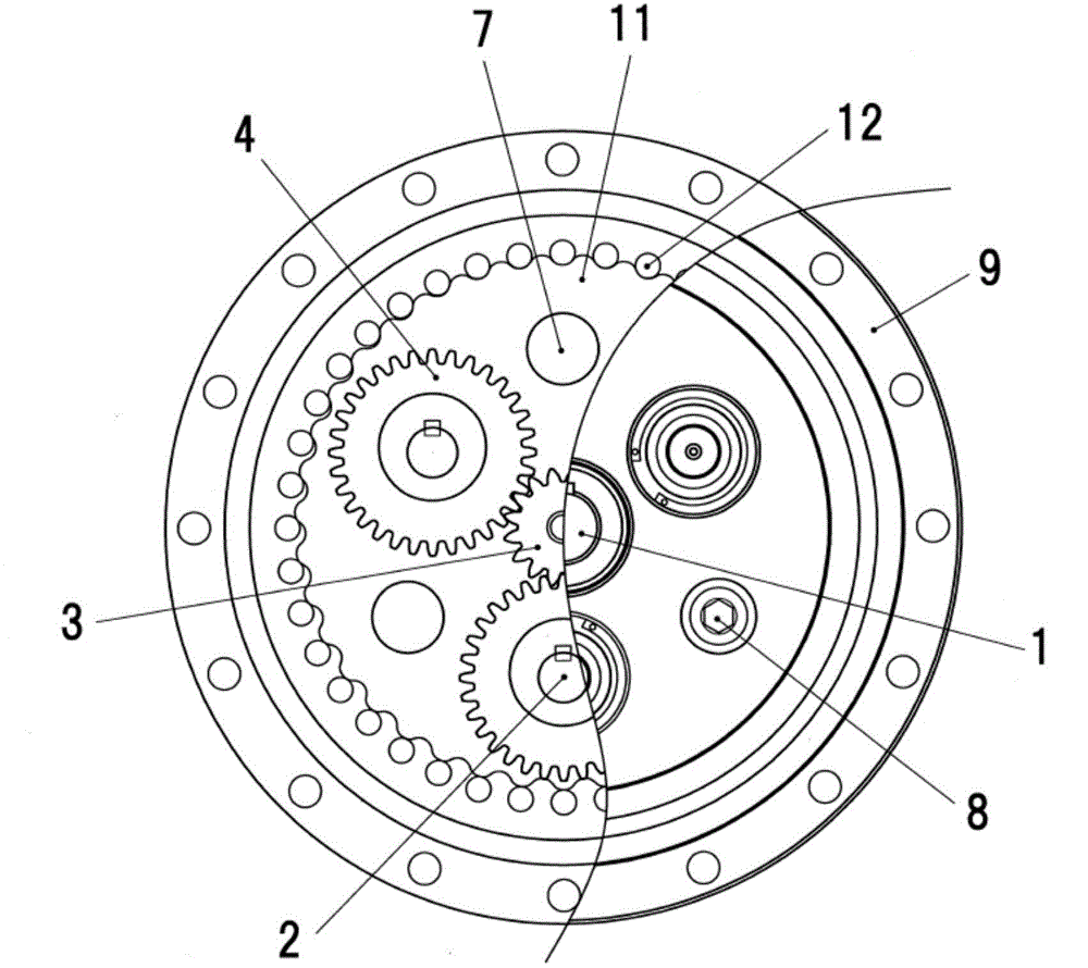
[0042] figure 1In Figure 4, 1-input shaft, 2-eccentric crankshaft, 3-sun gear, 4-transmission gear, 5-input side support body, 6-output side support body, 7-pillar, 8-bolt, 9-housing , 10-bearing, 11-external gear, 12-internal gear, 13-slot a, 14-slot b, 15-bearing outer ring, 16-bearing inner ring, 17-bearing b, 18-external gear b , 19-pin (internal teeth).

[0043] Such as figure 2 As shown, the present invention proposes an inscribed meshing gear device, which includes an external tooth gear with a cycloid tooth profile or a modified cycloid tooth profile, and an inner tooth with an arc tooth profile with more teeth than the external tooth gear The gear 12 has multiple eccentric crankshafts 2 supporting the swinging rotation of the external gear in order to enable the external gear to revolve in the internal gear 12, and further includes an input shaft 1, which is used as an input side power source, and a transmission gear 4, The transmission gear 4 is a spur gear, whic...


PUM


Abstract

The invention provides an inner-connection meshing type gear device. The inner-connection meshing type gear device comprises an outer-tooth gear in a cycloidal tooth shape or a finished cycloidal tooth shape, an arc-tooth-profile inner-tooth gear and a plurality of eccentric crankshafts, wherein the number of teeth of the inner-tooth gear is larger than that of the outer-tooth gear; and the eccentric crankshafts are arranged to enable the outer-tooth gear to revolve in the inner-tooth gear, and the eccentric crankshafts can support swinging and rotating of the outer-tooth gear. An input shaft serves as an input side power source. A spur gear serving as a transmission gear is used for transmitting power to the eccentric crankshafts. The positions of the input shaft and a meshing part of the transmission gear deviate towards the input side relative to an output side supporting body and are adjacent to the outer-tooth gear. The inner-connection meshing type gear device can be applied to various industries such as a multi-link robot, an industrial machine, a positioning device of a machining tool and other inner-connection meshing type gear devices needing high precision, inclination of the input shaft and a gap of a speed reduction gear are reduced, and high durability is achieved.

Description

technical field [0001] The invention relates to an internal meshing gear device, the external gear meshes with the internal gear and eccentrically swings and rotates through an eccentric crankshaft. Background technique [0002] At present, due to the large number of teeth in contact and meshing, and high rigidity, the internal meshing gear device is mostly used as a reducer in the joint mechanism of joint robots, the rotary drive mechanism of processing equipment, and the positioning mechanism of processing accessories. [0003] In this type of internal meshing gear device, the external tooth shape of the external tooth gear is a shape conforming to a cycloid curve, or the tooth shape is slightly modified in consideration of machining accuracy, assembly, durability, etc. Trimmed shape. In this device, the external gear keeps revolving by the eccentric amount determined by the eccentric crankshaft, and revolves while meshing with the internal gear, corresponding to the diff...

Claims


Application Information

Patent Timeline
IPC IPC(8): F16H1/32F16H57/023F16H57/08
CPCF16H1/32F16H57/023F16H57/08
Inventor 萩原秀雄木原蓝
Owner 亚杩拓精密机械(上海)有限公司
Why Eureka
Try Eureka