Optical fiber gyroscope with optical fiber ring adopting double-ring design

A fiber-optic gyroscope and fiber-optic ring technology, which is applied in Sagnac effect gyroscopes, gyroscopes/steering sensing devices, measuring devices, etc., can solve problems such as unsatisfactory results, unusable use, and large data volume, and achieves a solution to the problem. Temperature distribution symmetry problem, the effect of solving temperature drift

Active Publication Date: 2015-11-04
HARBIN ENG UNIV
View PDF4 Cites 18 Cited by
  • Summary
  • Abstract
  • Description
  • Claims
  • Application Information

AI Technical Summary

Problems solved by technology

Although these measures suppress the temperature drift to a certain extent, the effect is not ideal.
Theoretically, a single optical fiber ring adopts a complicated ring-wrapping process to achieve the same thermal disturbance on both sides of the fiber midpoint, but it is almost impossible to realize the actual winding. Although the intelligent algorithm can compensate the temperature drift well in the offline situation, the amount of data is large The real-time performance is so poor that it is almost unusable

Method used


Image

  • Optical fiber gyroscope with optical fiber ring adopting double-ring design
  • Optical fiber gyroscope with optical fiber ring adopting double-ring design
  • Optical fiber gyroscope with optical fiber ring adopting double-ring design

Examples


Embodiment Construction

[0016] The present invention will be described in further detail below in conjunction with the accompanying drawings.

[0017] The purpose of the present invention is to provide a fiber optic gyro device with better temperature stability and suitable for mass production.

[0018] The purpose of the present invention is achieved like this:

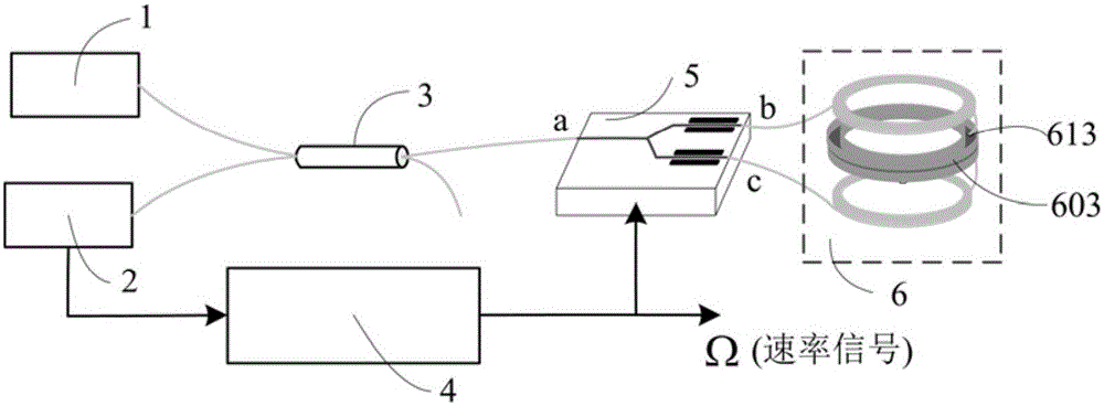
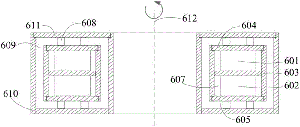
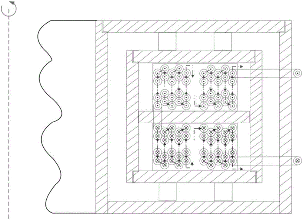
[0019] It includes a light source 1 connected by connecting optical fibers, a photoelectric detector 2, a polarization-maintaining fiber coupler 3, an all-digital closed-loop processing circuit 4, and an optical modulator 5. It also includes a pair of optical fiber rings and a matching heat insulation device. The interference component 6. The assembly method of the interference component is to take two identical optical fiber rings 601 and 602 and place them in two back-to-back heat conduction grooves 603 respectively, and one of the rings is turned 180° to ensure that each ring of the two optical fiber rings is symmetrical to each other. ...


PUM


Abstract

The invention discloses an optical fiber gyroscope with an optical fiber ring adopting a double-ring design. The optical fiber gyroscope comprises a light source, a photoelectric detector, an optical fiber coupling device, a signal processor, an optical modulator and an interference part, wherein the interference part comprises two optical fiber rings and a heat insulation device; the heat insulation device comprises an inner cavity and an outer cavity; a hard insulating ring is mounted between the inner cavity and the outer cavity; a heat guide groove is mounted in the inner cavity; the two optical fiber rings are symmetrically mounted on the two sides of the heat guide groove; a small hole is formed in the heat guide groove; corresponding ends of the two optical fiber rings are spliced and a splicing point is located in the small hole of the heat guide groove; leading-out ends of the two optical fiber rings are led out from other small holes of the heat guide groove and penetrate through the inner cavity and the outer cavity respectively; the leading-out end of one optical fiber ring is connected with a first output end of the optical modulator and the leading-out end of the other optical fiber ring is connected with a second output end of the optical modulator; and the small holes on the heat guide groove are sealed, and the inner cavity and the outer cavity are sealed. The optical fiber gyroscope has the advantages of high temperature stability.

Description

technical field [0001] The invention relates to the fields of optical fiber sensing, optical fiber gyroscope, fiber winding technology and thermal analysis, and in particular to an optical fiber gyroscope with double-ring design for an optical fiber ring suitable for harsh temperature conditions. Background technique [0002] Fiber optic gyroscope is a new generation of angular velocity sensor based on the Sagnac effect. Compared with the traditional mechanical rotor gyroscope, the fiber optic gyroscope has the advantages of all solid state, short start-up time, no rotating parts, long life, and simple structure. Based on this, the fiber optic gyroscope has become the mainstream instrument required in the inertial field. Therefore, it is very important to further improve the accuracy and reliability of fiber optic gyro in the field of inertial devices. The accuracy and reliability of the fiber optic gyroscope depend greatly on the performance and reliability of its importan...

Claims


Application Information

Patent Timeline
Patent Type & Authority Applications(China)
IPC IPC(8): G01C19/72
CPCG01C19/721
Inventor 李绪友凌卫伟许振龙张帆张志永刘攀刘猛韩鹏何昆鹏
Owner HARBIN ENG UNIV
Why Eureka
Try Eureka