Multifunctional gas sensor testing system

A gas sensor and test system technology, applied in standard gas analyzers, control/regulation systems, and analysis of gas mixtures, etc., can solve the problems of sudden increase in test circuit current, low detection efficiency, single test function, etc., and achieve accurate response time and recovery time, improve test efficiency, and improve test accuracy

Active Publication Date: 2015-11-04
HUBEI UNIV
View PDF13 Cites 43 Cited by
  • Summary
  • Abstract
  • Description
  • Claims
  • Application Information

AI Technical Summary

Problems solved by technology

[0011] The sensor test system reported in the above literature (1-4) also has problems such as single test function and slow air intake
Although the sensor test system reported in Document 5 solves the problem of slow air intake, the test chamber is too small and can only test the performance parameters of a single sensor, making its detection efficiency low
In addition, the device directly monitors the resistance of the sensor to be tested through a resistance meter. When the resistance of the sensor to be tested drops greatly, the current in the test circuit will increase sharply, causing the sensor to heat up and destroy the accuracy of the detection result.

Method used


Image

  • Multifunctional gas sensor testing system
  • Multifunctional gas sensor testing system
  • Multifunctional gas sensor testing system

Examples


Embodiment Construction

[0052] The embodiments of the present invention will be further described below in conjunction with the accompanying drawings. Examples of the embodiments are shown in the accompanying drawings, wherein the same or similar symbols throughout represent the same or similar elements or elements with the same or similar functions. The embodiments described below by referring to the accompanying drawings are exemplary and are intended to explain the present invention, but should not be construed as limiting the present invention. Any modifications, equivalent replacements or Improvements, etc., should be included within the scope of the claims of the present invention, and those not described in detail in this technical solution are all known technologies.

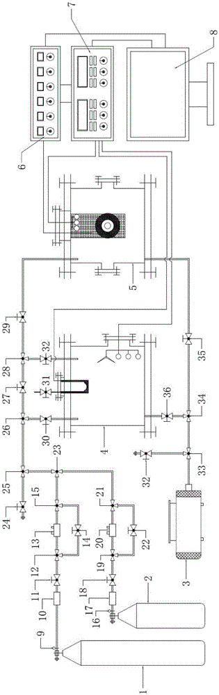
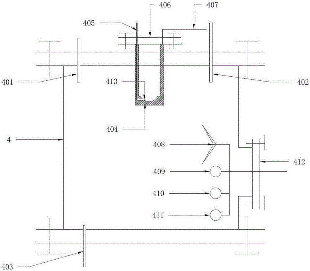
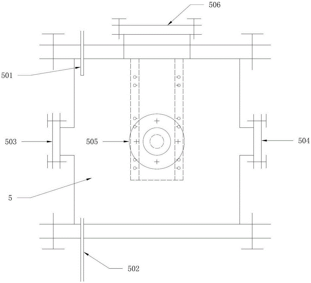
[0053] as attached figure 1 As shown, a multifunctional gas sensor testing system of the present invention includes: a gas distribution mechanism and a gas distribution chamber 4 , a testing chamber 5 , a control system, a test...


PUM


Abstract

The invention discloses a multifunctional gas sensor testing system. The multifunctional gas sensor testing system comprises a gas distribution mechanism and a gas distribution chamber, a testing chamber, a control system, a testing mechanism and a vacuum pump, wherein the gas distribution mechanism is used for preparing standard-concentration gas and background gas for the gas distribution chamber; prepared standard-concentration testing gas is stored in the testing chamber and the testing chamber is used for testing a sensor sensitive property under standard concentration of gas to be tested; and the control system is used for controlling gas preparation in the gas distribution chamber and the testing chamber, and comprises temperature and humidity control, gas pressure or vacuum degree control, gas mass and flow control, on-off control of each gas-path solenoid valve, starting/stopping control of the vacuum pump, starting/stopping control of a stirring fan, and testing process control of a detected sensor. According to the multifunctional gas sensor testing system disclosed by the invention, rapid contact of the sensor and standard gas is realized by automatically preparing the standard-concentration gas, and the temperature and humidity of a sensor testing environment also can be controlled; and synchronous testing of electric gas responding of the plurality of sensors and optical gas responding of the single sensor also can be realized.

Description

technical field [0001] The invention relates to a multifunctional gas sensor testing system, in particular to a multifunctional gas sensor performance testing system, belonging to the technical field of gas sensor testing. Background technique [0002] Gas sensors (gas sensors or gas sensors) can be used for real-time monitoring and safety alarms of flammable, explosive, toxic gases, and various gaseous indicators. They have been widely used in environmental monitoring, industrial production, military safety, and medical treatment. areas such as health and energy. The temperature and humidity stability of the sensor and its response sensitivity to the gas on the standby side, response / recovery speed and selectivity are key indicators for judging its performance. With the development of related fields, people put forward higher requirements for the measurement accuracy, accuracy and temperature and humidity stability of gas sensors. [0003] The gas sensor test system is ma...

Claims


Application Information

Patent Timeline
Patent Type & Authority Applications(China)
IPC IPC(8): G01N33/00G05D27/02
CPCG01N33/0006G05D27/02
Inventor 顾豪爽王钊胡永明杨树林
Owner HUBEI UNIV
Why Eureka
Try Eureka