Vacuum arc-extinguishing chamber, coil-type contact element and current coil

A technology of current coil and contact assembly, which is applied in the direction of high-voltage/high-current switches, circuits, electric switches, etc., can solve the problems of large overall resistance, long conductive path of current coil, uneven distribution of the overall magnetic field, etc., and achieve a small overall circuit , Improve the breaking performance and the effect of uniform magnetic field distribution

Active Publication Date: 2015-11-04
TIANJIN PINGGAO INTELLIGENT ELECTRIC +3
View PDF6 Cites 7 Cited by
  • Summary
  • Abstract
  • Description
  • Claims
  • Application Information

AI Technical Summary

Problems solved by technology

However, the conductive path of the current coil with half coils arranged on the upper and lower layers is too long, the overall resistance is relative

Method used


Image

  • Vacuum arc-extinguishing chamber, coil-type contact element and current coil
  • Vacuum arc-extinguishing chamber, coil-type contact element and current coil
  • Vacuum arc-extinguishing chamber, coil-type contact element and current coil

Examples


Embodiment Construction

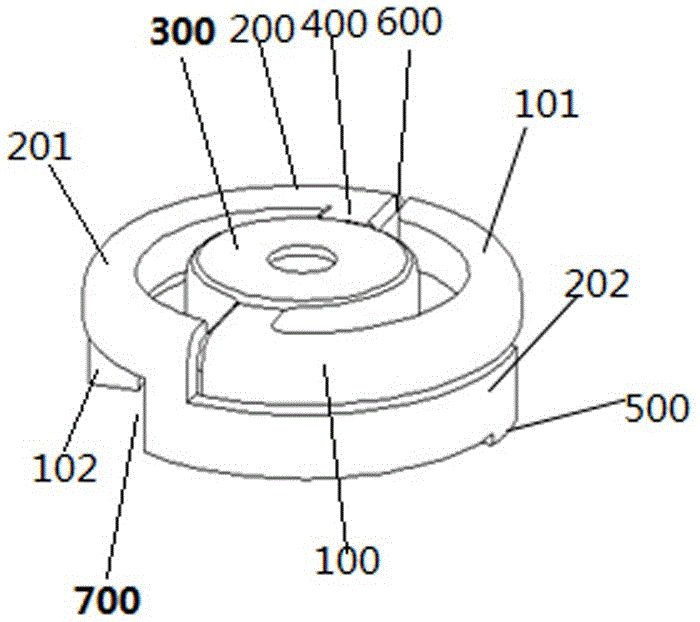
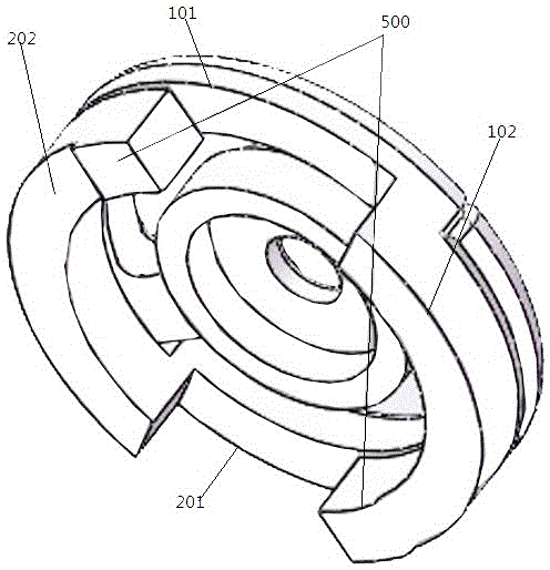
[0028] Such as figure 1 , figure 2As shown, an embodiment of a current coil for a coiled contact assembly, the current coil in this embodiment includes a first sub-coil 100 and a second sub-coil 200 that extend around the circumferential direction and are arranged in parallel, and each sub-coil includes The upper coil section for conductive connection with the conductive rod of the contact assembly and the lower coil section for conductive connection with the contact blade of the contact assembly that are staggered in the vertical direction and conductively connected in series, the first sub-coil 100 includes The first upper coil segment 101 and the first lower coil segment 102, the second sub-coil 200 includes the second upper coil segment 201 and the second lower coil segment 202, wherein the first upper coil segments 101 of the first sub-coil 100 are arranged at intervals Above the second lower coil segment 202 of the second sub-coil 200, the second upper coil segment 201...


PUM


Abstract

The invention provides a vacuum arc-extinguishing chamber, a coil-type contact element and a current coil. The current coil comprises two branch coils extending in the circumferential direction and arranged in parallel. Each branch coil comprises an upper coil section and a lower coil section which are distributed to be staggered in an upper direction and a lower direction and in series conductive connection. The two upper coil sections are two half turning coil sections arranged symmetrically with respect to the center line of the current coil. The two lower coil sections of the two branch coils are two quarter turning coil sections arranged symmetrically with respect to the center line of the current coil. Each branch coil is a three-fourths turning coil section formed by the quarter turning coil section and the half turning coil section. A current in each of two parallel connection branches formed by the two branch coils passes by the circumferential path of the three-fourths turning coil section, the current path is short, the whole circuit is small, the upper coil section and the lower coil section are arranged in central symmetry with respect to the center line of the current coil respectively, and thus distribution of the magnetic field generated by the current coil is uniform.

Description

technical field [0001] The invention relates to a vacuum interrupter, a coil type contact assembly and a current coil thereof. Background technique [0002] At present, sulfur hexafluoride circuit breakers occupy a dominant position in high-voltage and ultra-high-voltage circuit breakers. Sulfur hexafluoride gas has good insulation performance and excellent arc extinguishing performance, and its compressive strength is 2.5 times that of nitrogen gas under the same pressure. However, sulfur hexafluoride gas is a greenhouse gas, and its single-molecule greenhouse effect is 22,000 times that of carbon dioxide. It is one of the six greenhouse gases that are prohibited from being emitted in the "Kyoto Protocol", and it is recommended to be completely banned by 2030. Sulfur hexafluoride gas. Therefore, vacuum circuit breakers have gradually become the future development direction of circuit breakers due to their advantages of less environmental pollution, less maintenance wor...

Claims


Application Information

Patent Timeline
IPC IPC(8): H01H33/664
CPCH01H33/6643H01H33/6644
Inventor 张雪敏王晓琴施大成李文艺李敏葛媛媛张国跃钟建英袁端磊
Owner TIANJIN PINGGAO INTELLIGENT ELECTRIC
Why Eureka
Try Eureka