A magnetization decoupling axial flux switching dual-rotor motor

A dual-rotor motor, axial magnetic flux technology, applied in the direction of magnetic circuit rotating parts, electrical components, electromechanical devices, etc., can solve the problems of increasing the axial length of the motor, permanent magnet flux leakage, and permanent magnet flux leakage increase. , to reduce the axial size, improve the power density, and increase the air gap magnetic density.

Active Publication Date: 2017-10-20
JIANGSU UNIV
View PDF2 Cites 0 Cited by
  • Summary
  • Abstract
  • Description
  • Claims
  • Application Information

AI Technical Summary

Problems solved by technology

However, in the axial field flux switching motor proposed in this patent, the permanent magnet only exists in the middle of the stator unit, and the volume of the permanent magnet that can be accommodated is very limited.
In order to obtain a larger air gap flux density, the axial length of the motor stator can only be increased, which will lead to an increase in the axial length of the motor, an increase in the flux leakage of the permanent magnet, and it is difficult to increase the power density of the motor
Another patent (application number: 201310252069.9) proposes a dual-rotor motor that can solve the problem of permanent magnet flux leakage, but still does not provide a reasonable solution to the problem of increasing the axial length of the motor
Moreover, the magnetic circuits of the two rotors in this patent are severely coupled when the motor is running. The two rotors can only run at the same speed, and the independent operation of the rotors on both sides cannot be realized. In essence, it is still a single rotor, but the rotor is divided into two parts and distributed in the stator. both sides

Method used


Image

  • A magnetization decoupling axial flux switching dual-rotor motor
  • A magnetization decoupling axial flux switching dual-rotor motor
  • A magnetization decoupling axial flux switching dual-rotor motor

Examples


Embodiment Construction

[0038] The following will clearly and completely describe the technical solutions in the embodiments of the present invention with reference to the drawings in the embodiments of the present invention.

[0039] In the description of the present invention, it should be understood that the present invention specifies "left" and "right" directions in the direction of the motor shaft, while the radial direction of the motor specifies the orientations of "inner" and "outer". In addition, the terms "center", "portrait", "transverse", "top", "bottom", "front", "rear", "left", "right", "vertical", "horizontal", "top ", "bottom", "inner", "outer" and other indicated orientations or positional relationships are based on the orientations or positional relationships shown in the drawings, and are only for the convenience of describing the present invention and simplifying the description, rather than indicating or implying Any device or element must have a specific orientation, be constru...


PUM


Abstract

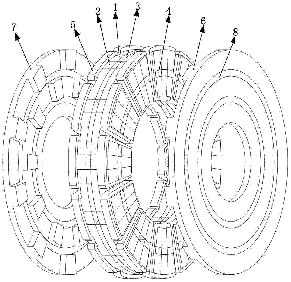
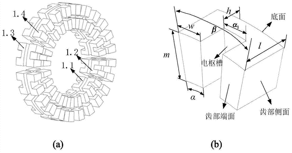
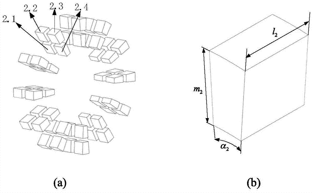
The invention discloses a magnetically increasing and decoupling axial flux switching dual-rotor motor. The rotor of the motor adopts a disc salient pole structure, and the stator is embedded between the first rotor and the second rotor, which is a salient pole structure, including Stator core, tangential permanent magnet, magnetizing permanent magnet, radial permanent magnet, armature winding. In the present invention, since the magnetization permanent magnet is added to the center surface of the motor stator core, the entire motor magnetic circuit is divided into left and right parts. The coupling of the rotor magnetic circuit enables the left and right rotors to operate independently. At the same time, the magnetized permanent magnet, the tangential permanent magnet and the radial permanent magnet produce a magnetization effect, thereby increasing the air gap flux density of the motor and increasing the power density of the motor. There is neither winding nor permanent magnet on the rotor. It has a simple structure and is suitable for high-speed operation. The disc structure rotor requires less iron core material, low cost, small moment of inertia, and has the characteristics of quick start.

Description

technical field [0001] The invention relates to a magnetic flux switching motor, in particular to a magnetization decoupling type axial flux switching dual-rotor motor, which belongs to the technical field of permanent magnet motors. Background technique [0002] Axial field motors are also called disc motors. Compared with radial field motors, this type of motor has the characteristics of a flat air gap, radial placement of current-carrying conductors, and axial distribution of the air gap magnetic field. The rotor heat dissipation condition of the magnetic field motor is not good, and the utilization rate of the rotor core is not high. The world's first motor was an axial field motor, but due to the limitations of materials and manufacturing processes at that time, the disc motor could not be further developed. With the development of modern material science and the improvement of manufacturing technology, the problems that restricted the development of axial magnetic fie...

Claims


Application Information

Patent Timeline
Patent Type & Authority Patents(China)
IPC IPC(8): H02K16/02H02K1/17H02K1/14H02K1/24
Inventor 全力殷佳宁朱孝勇项子旋
Owner JIANGSU UNIV
Why Eureka
Try Eureka