Electrical machine having a cooling device, and method for producing said electrical machine

A cooling device and cooling medium technology, applied in cooling/ventilation devices, electromechanical devices, manufacturing stator/rotor bodies, etc., can solve the problems of increased heat transfer resistance, cooling jacket manufacturing and assembly costs, etc. Improved cooling efficiency, the effect of simple design solutions

Active Publication Date: 2015-11-04
SCHAEFFLER TECH AG & CO KG
View PDF6 Cites 2 Cited by
  • Summary
  • Abstract
  • Description
  • Claims
  • Application Information

AI Technical Summary

Problems solved by technology

The manufacture and assembly of such cooling jackets is very complex and many small cavities arise between the cooling jacket and the stator due to surface roughness, which increase the heat transfer resistance

Method used


Image

  • Electrical machine having a cooling device, and method for producing said electrical machine

Examples


Embodiment Construction

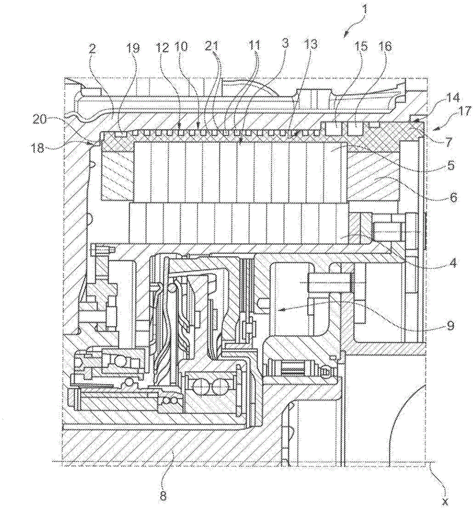
[0028] The single FIGURE shows, in partial section, an electric machine 1 with a housing 2 , a stator 3 fixedly accommodated therein, and a rotor 4 rotatable about an axis of rotation x. The stator is formed from a soft magnetic core 5 and a winding accommodated therein, which winding has winding ends 6 . The plastic body 7 seals the stator 3 in the direction of the housing 2 . A friction clutch 9 is arranged between the drive shaft 8 and the rotor 4 , which is arranged radially and axially inside the rotor 4 .

[0029] A cooling device 10 is arranged between the housing 2 and the stator 3 . It is formed by cooling channels 12 introduced as recesses 11 into the plastic body. A cooling medium, which dissipates the heat loss heat of the stator, is conducted into the cooling channel. The recess 11 is arranged helically on the outer periphery of the plastic body 7 along the axis of rotation x and covers substantially the entire axial width of the stator 3 . In order to produce...


PUM


Abstract

The invention relates to an electrical machine (1), and to a method for producing said electrical machine, said electrical machine having a housing (2) and a stator (3), which is held on said housing, and at least one rotor (4), which is arranged radially within the stator (3), a plastic body (7), which surrounds a soft-magnetic body (5) of the stator (3) at least radially on the outside, and a cooling device (10) between the stator (3) and the housing (2). In order to improve the cooling device (10), at least one recess (11), which carries a cooling medium, is made at least partially in the outer circumference of the plastic body (7) between the housing (2) and the stator (3).

Description

technical field [0001] The invention relates to an electric machine and a method for its production, the electric machine having a housing, a stator accommodated on the housing and at least one rotor arranged radially inside the stator and a plastic body surrounding a soft-magnetic core of the stator at least radially outwardly and a cooling device between the stator and the housing. Background technique [0002] For example, electric machines in the form of electric motors and / or generators in drives of motor vehicles have, in a corresponding construction, stators with soft magnetic cores, coils made of copper wire or copper rods wound in or between the stators The windings and the rotor are torsionally arranged in the stator. When the coil is energized, in addition to converting electrical energy into mechanical energy and vice versa, the coil also generates thermal energy, which can act as a thermal load leading to a temperature increase in the components and thus to dam...

Claims


Application Information

Patent Timeline
Patent Type & Authority Applications(China)
IPC IPC(8): A99Z99/00
CPCH02K5/20H02K9/19H02K5/203H02K1/04H02K15/02
Inventor 米夏埃尔·科贝斯马里亚·霍兰阿希姆·韦伯沃尔夫冈·希尔
Owner SCHAEFFLER TECH AG & CO KG
Why Eureka
Try Eureka