gas cooler

A gas cooler and cooling chamber technology, which is applied in gaseous chemical plating, chemical instruments and methods, lighting and heating equipment, etc., can solve the problems of increasing driving force, increasing sliding resistance, and increasing the overall size of the device.

Active Publication Date: 2017-07-11
JFE STEEL CORP
View PDF1 Cites 0 Cited by
  • Summary
  • Abstract
  • Description
  • Claims
  • Application Information

AI Technical Summary

Problems solved by technology

In addition, if the sealing performance of the sliding part is enhanced in order to improve the sealing effect, the sliding resistance increases accordingly, and the driving force needs to be further increased.
[0011] Therefore, in the drive mechanism for driving the conventional dust removal plate, there is a problem that the entire device is enlarged in order to realize stable drive.

Method used


Image

  • gas cooler

Examples


Embodiment Construction

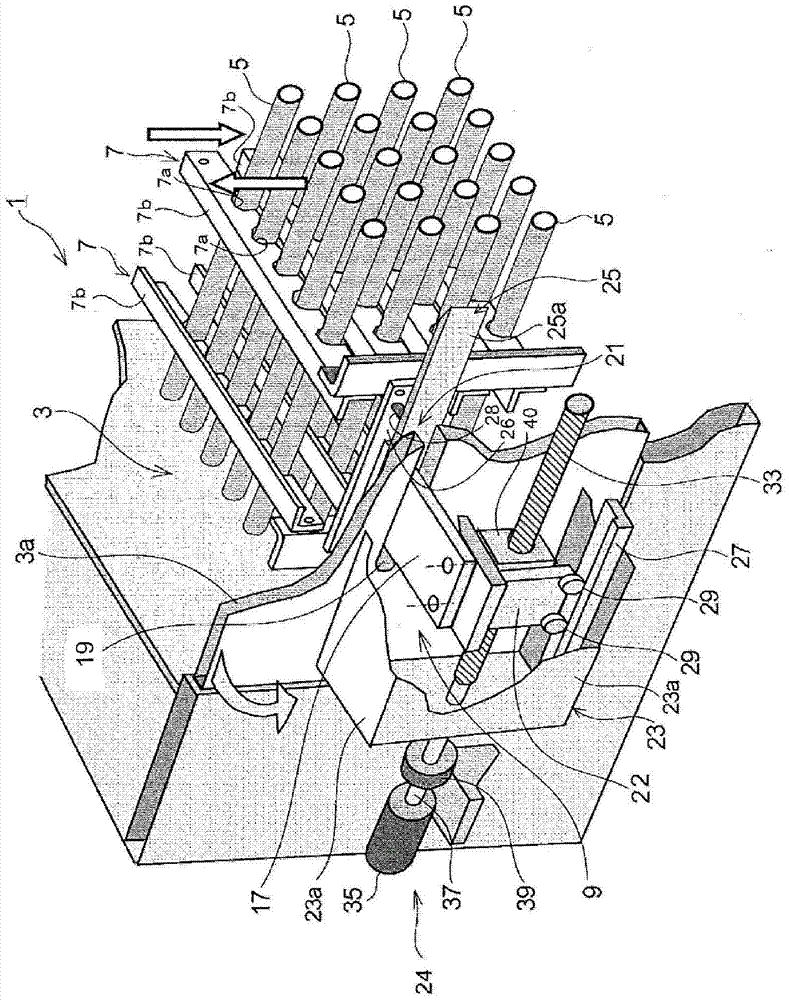
[0030] based on figure 1 The gas cooler 1 according to this embodiment will be described.

[0031] like figure 1 As shown, the gas cooler 1 of this embodiment has: a plurality of cooling pipes 5, which are arranged in parallel in the cooling chamber 3 for gas circulation; and a reciprocating mechanism 9 that reciprocates the dust removal component 7 along the axial direction of the cooling pipe 5 .

[0032] Each configuration will be described in detail below.

[0033]

[0034] Cooling chamber 3 is a chamber for the circulation of exhaust gas, such as figure 1 Flow in the direction perpendicular to the cooling pipe 5 (from bottom to top, or from top to bottom) as shown by the arrow.

[0035] The side wall 3a of the cooling chamber 3 has a door structure and can be opened and closed as shown by the arrow in the figure. By making the side wall 3a openable and closable, maintenance such as replacement of the dust removal member 7 and internal inspection become easy.

[00...


PUM

PropertyMeasurementUnit
melting pointaaaaaaaaaa

Abstract

The present invention provides a gas cooler capable of being reduced in size, capable of preventing exhaust gas from leaking to the outside, and capable of stably removing dust. The gas cooler (1) of the present invention has: a plurality of cooling pipes (5), which are arranged in the cooling chamber (3); dust removal parts (7), which are slidably arranged on the peripheral surface of the cooling pipes; reciprocating A moving mechanism (9), which makes the dust removal component reciprocate along the axial direction of the cooling pipe. The reciprocating mechanism is provided with: a holding member (17), which holds the dust removal member reciprocally movable and protrudes in a direction intersecting with the axial direction of the cooling pipe; an opening (19), which is provided on the side wall (3a) of the cooling chamber ), which enables the holding member to protrude from the side of the cooling chamber and reciprocates; a sealing mechanism (21), which prevents the gas in the cooling chamber from leaking to the outside; a moving body (22), which supports the holding member protruding from the opening and capable of reciprocating movement; and a drive mechanism (24) that reciprocates the moving body.

Description

technical field [0001] The present invention relates to, for example, a gas cooler (exhaust gas cooling device) for cooling the exhaust gas of a facility that manufactures high-concentration silicon steel strips by siliconizing treatment by CVD (chemical vapor deposition). Gas cooler for gas cooling. Background technique [0002] The exhaust gas of the furnace equipment for manufacturing high silicon steel strip contains ferrous chloride (FeCl 2 , hereinafter referred to as ferric chloride), this substance has physical properties of a boiling point of 1024°C and a melting point of 670°C. [0003] When the exhaust gas is rapidly cooled from the temperature in the furnace to below the melting point, ferric chloride is produced as a fine powder in the exhaust gas. When the exhaust gas is further cooled from this temperature by the gas cooler, ferric chloride (dust) adheres to the heat transfer surface of the gas cooler. Therefore, a dust removal device is required in the gas...

Claims


Application Information

Patent Timeline
Patent Type & Authority Patents(China)
IPC IPC(8): F28G1/08B08B1/00C23C16/44
CPCB08B1/008B08B9/023C23C16/4412F28G1/08
Inventor 古贺泰成富永健一堤道明
Owner JFE STEEL CORP
Why Eureka
Try Eureka