A pneumatic vibration device

A technology of pneumatic vibration and air source, applied in the direction of fluid using vibration, etc., can solve the problems affecting the life of the vibration device, the limit of the service life, the large volume of the product, etc., and achieve the effect of large vibration force, stable output force and small volume.

Inactive Publication Date: 2017-12-12
王洪波
View PDF7 Cites 0 Cited by
  • Summary
  • Abstract
  • Description
  • Claims
  • Application Information

AI Technical Summary

Problems solved by technology

[0002] At present, the existing vibration devices in China have their own defects. For example, the vibration device that relies on the centrifugal force to generate vibration has a large product volume, complicated installation, and high noise. The cumbersome structure also affects the life of the vibration device; relying on the valve body to control the cylinder The vibration device that realizes vibration has a wide range of applications, but under high-frequency operation, the replacement of vulnerable parts becomes the focus of work, and the service life is limited; the vibration device that relies on the action of magnets and springs to generate vibration force has low frequency and large noise. Easy to wear, requires a large amount of lubrication

Method used


Image

  • A pneumatic vibration device
  • A pneumatic vibration device

Examples


Embodiment Construction

[0018] The principles and features of the present invention are described below in conjunction with the accompanying drawings, and the examples given are only used to explain the present invention, and are not intended to limit the scope of the present invention.

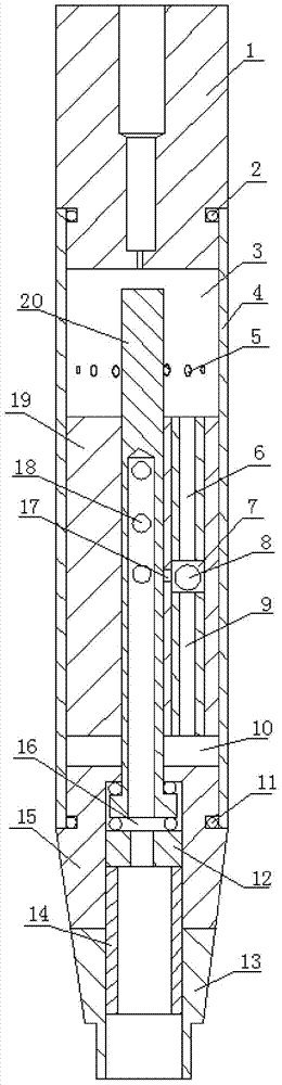
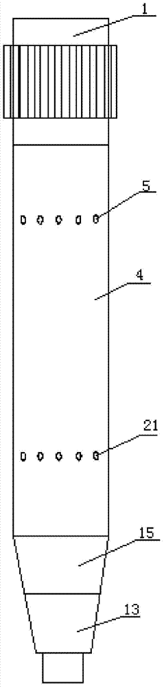
[0019] like figure 1 and figure 2 Shown, a kind of pneumatic vibrating device is characterized in that: comprises cylinder 4, piston 19, transition joint 15, air source joint 13, end cap 1 and the central axis tube 20 of one end sealing, and piston 19 is positioned at cylinder 4 Inner cavity, the inner cavity of the cylinder body 4 is divided into the first chamber 3 and the second chamber 10 by the piston 19, and the circumferential side walls of the cylinder body 4 corresponding to the first chamber 3 and the second chamber 10 are respectively opened There are a plurality of first exhaust holes 5 and second exhaust holes 21 communicating with the inner cavity of the cylinder body 4. The end cover 1 is fixedly co...


PUM


Abstract

The invention relates to a vibration device, in particular to a novel pneumatic vibration device. Collision contact-free reciprocating motion of a piston, an end cover and a transition connector in a cylinder is achieved by filling the novel pneumatic vibration device with compressed air, and a vibration effect is generated. The novel pneumatic vibration device has the advantages of being simple in structure, large in vibration force, high in frequency, low in noise, small in size, long in service life, stable in operating and stable in output force.

Description

technical field [0001] The invention relates to a vibration device, in particular to a pneumatic vibration device. Background technique [0002] At present, the existing vibration devices in China have their own defects. For example, the vibration device that relies on the centrifugal force to generate vibration has a large product volume, complicated installation, and high noise. The cumbersome structure also affects the life of the vibration device; relying on the valve body to control the cylinder The vibration device that realizes vibration has a wide range of applications, but under high-frequency operation, the replacement of vulnerable parts becomes the focus of work, and the service life is limited; the vibration device that relies on the action of magnets and springs to generate vibration force has low frequency and large noise. Easy to wear and requires a large amount of lubrication. Contents of the invention [0003] The technical problem to be solved by the pr...

Claims


Application Information

Patent Timeline
Patent Type & Authority Patents(China)
IPC IPC(8): B06B1/18
Inventor 王洪波
Owner 王洪波
Why Eureka
Try Eureka