

Snap spring mounting mechanism of universal motor snap spring assembling machine
An assembly machine, general-purpose technology, used in electromechanical devices, manufacturing motor generators, electrical components, etc., can solve problems such as laborious automation, achieve good automation, reduce labor costs, and good versatility.
- Summary
- Abstract
- Description
- Claims
- Application Information
AI Technical Summary
Problems solved by technology
Method used
Image

Examples
Embodiment 1
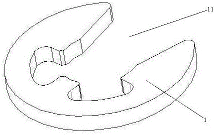
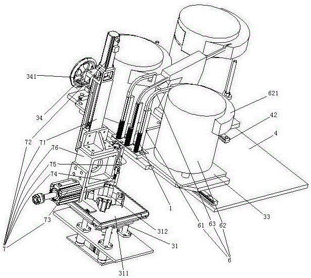
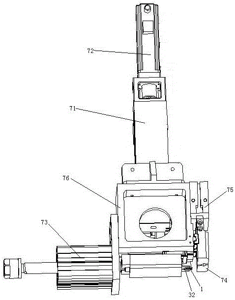
[0032] Embodiment one, see figure 2 , a general-purpose motor circlip assembly machine circlip mechanism, including a frame 4, a fixing mechanism 31, a base 33, a circlip feeding mechanism 6, a third drive mechanism 34 and a fourth drive mechanism 7. The frame 4 is provided with slide rails 42 . The slide rail 42 extends in the left-right direction. The slide rail 42 is located behind the fixing mechanism 31 . The fixing mechanism 31 includes a panel 311 . A fixing hole 312 is defined on the panel 311 . The fixing mechanism 31 fixes the motor through adsorption by the electromagnet. The base 33 is slidably connected to the slide rail 42 . The snap spring feeding mechanism 6 is located at the rear side of the fixing mechanism 31 . There are 3 spring feeding mechanisms 6. The spring feeding mechanism 6 is arranged on the base 33 . The circlip feeding mechanism 6 includes a circlip threading connecting rod 61 , a circlip vibrating plate 62 and a slide bar 63 . The jumpe...
Embodiment 2
[0039] Embodiment two, the difference with embodiment one is:
[0040] see Figure 7 , replace the handle with the motor 5 to drive the screw 342 (see Figure 5 ), that is, the driving part is a motor. The motor 5 includes a rotating shaft 51 and a motor housing 52 . The rotating shaft 51 is supported by the motor housing 52 through two bearings 55 . An oil filling chamber 56 is formed between the motor housing 52 and the two bearings 55 . A first gear 58 and a second gear 57 are arranged in the oil filling chamber 56 . The first gear 58 and the second gear 57 mesh together. The first gear 58 is connected with the rotating shaft 51 . The second gear 57 is rotationally connected with the motor housing 52 through a short shaft 571 .
[0041] see Figure 8 , the first gear 58 is provided with a refueling mechanism 8 . The number of refueling mechanisms 8 is equal to the number of teeth of the first gear 58 .
[0042] see Figure 9 , The refueling mechanism 8 includes a...
Embodiment 3
[0047] Embodiment three, the difference with embodiment two is:
[0048] see Figure 11 , each circlip vibrating plate 62 is provided with a tilt self-off switch 9. Tilt self-cutting switch 9 is used for controlling circlip vibrating plate 62 to stop vibrating. The tilt self-cutting switch 9 includes a shell 91 and a connecting pin 92 . The shell 91 is fixedly connected with the circlip vibrating plate 62 .
[0049] see Figure 12 , The tilt self-disconnecting switch 9 also includes a power-disconnecting spring 93 , a conductive sheet 94 , a weight guide cavity 95 , a weight 96 , a swing arm 97 and a barb 98 .
[0050] The shell 91 is made of insulating material, specifically made of plastic. The shell 91 is connected with the frame 2 together. The housing 91 is provided with an assembly cavity 911 . A recess 915 is formed in the middle of the bottom wall of the assembly cavity 911 .
[0051] There are two connecting pins 92. The two connecting pins 92 are distributed...
PUM
 Abstract
Description
Claims
Application Information