Offset detection and control method for spiral hole milling device
A helical milling hole and control method technology, which is applied in the direction of manufacturing tools, measuring/indicating equipment, metal processing machinery parts, etc., can solve the problems of difficulty in ensuring accuracy and inability to detect the actual value of eccentricity, etc., so as to reduce scrap rate and processing accuracy The effect of reduced requirements and high degree of automation
- Summary
- Abstract
- Description
- Claims
- Application Information
AI Technical Summary
Problems solved by technology
Method used
Image

Examples
Embodiment 1
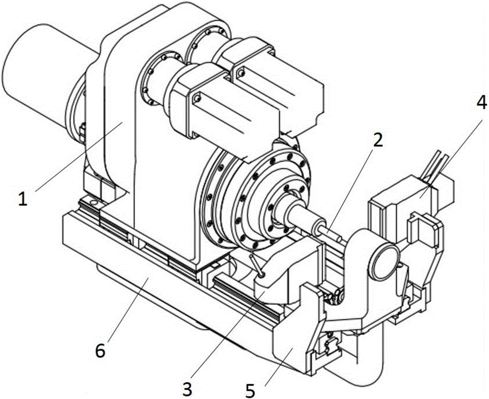
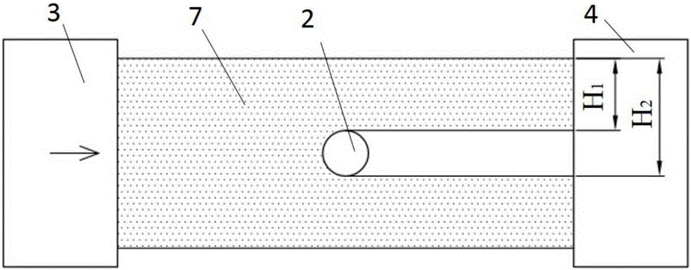
[0051] Such as figure 1 As shown, the laser detection device 8 includes an emitter 3 and a receiver 4. The emitter 3 and the receiver 4 are connected to the base 6 of the automatic helical milling device 1 through a bracket 5. The automatic helical milling device can realize the rotation of the tool and the Revolution, axial feed and automatic eccentric adjustment functions. The nominal diameter of the machining hole is D=10mm, the tolerance range is 0~+0.05mm, and the nominal diameter of the tool is d 0 = 6mm. Specific steps are as follows:
[0052] a. The laser detection device 8 is installed on both sides of the front of the helical milling device 1 through the bracket 5 to form a detection area 7, so that the laser direction in the detection area 7 is perpendicular to the cutter 2;
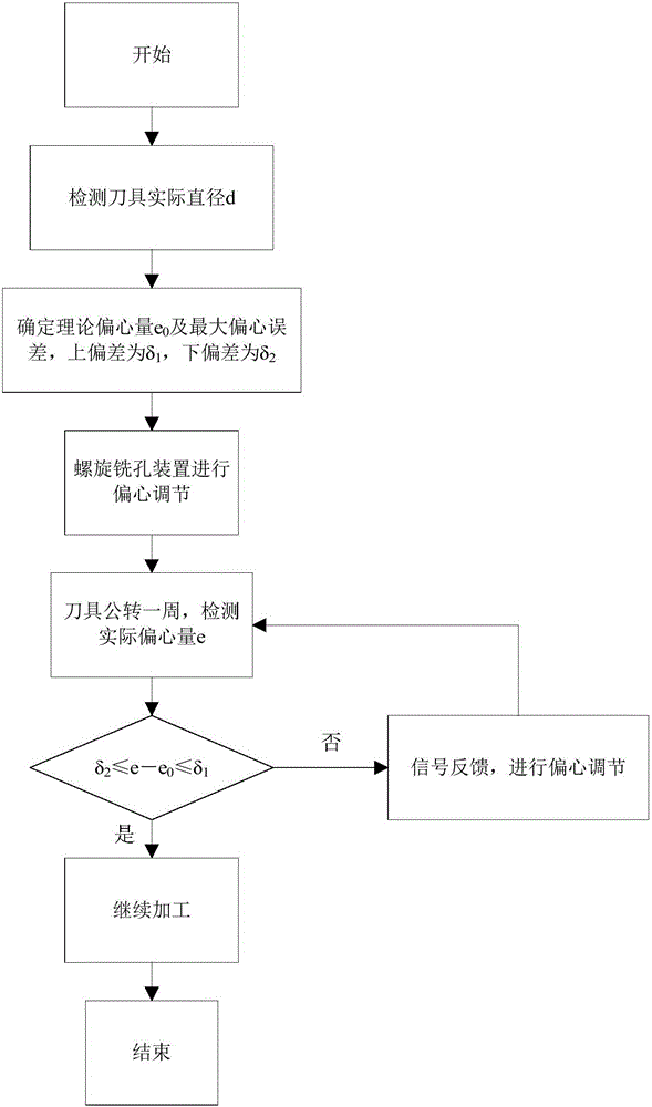
[0053] b. Start the feeding device of the helical milling device 1, so that the cutting edge of the tool 2 is located in the detection area 7;
[0054] c. The tool 2 rotates on its own, an...
PUM
 Abstract
Description
Claims
Application Information
 - Generate Ideas
- Intellectual Property
- Life Sciences
- Materials
- Tech Scout
- Unparalleled Data Quality
- Higher Quality Content
- 60% Fewer Hallucinations
Browse by: Latest US Patents, China's latest patents, Technical Efficacy Thesaurus, Application Domain, Technology Topic, Popular Technical Reports.
© 2025 PatSnap. All rights reserved.Legal|Privacy policy|Modern Slavery Act Transparency Statement|Sitemap|About US| Contact US: help@patsnap.com