Rotated quadrotor

A technology for tilting quadrotors and aircraft, applied in aircraft, rotorcraft, aircraft parts, etc., can solve problems such as performance changes and increased resistance of quadrotors, and achieve the effects of simple structure, reduced resistance, and increased flight speed.

A technology for tilting quadrotors and aircraft, applied in aircraft, rotorcraft, aircraft parts, etc., can solve problems such as performance changes and increased resistance of quadrotors, and achieve the effects of simple structure, reduced resistance, and increased flight speed.

CN105035313AActive Publication Date: 2015-11-11BEIHANG UNIV

Image

  • Rotated quadrotor
  • Rotated quadrotor
  • Rotated quadrotor

Examples


Embodiment Construction

[0028] The present invention will be further described in detail below with reference to the drawings and embodiments.

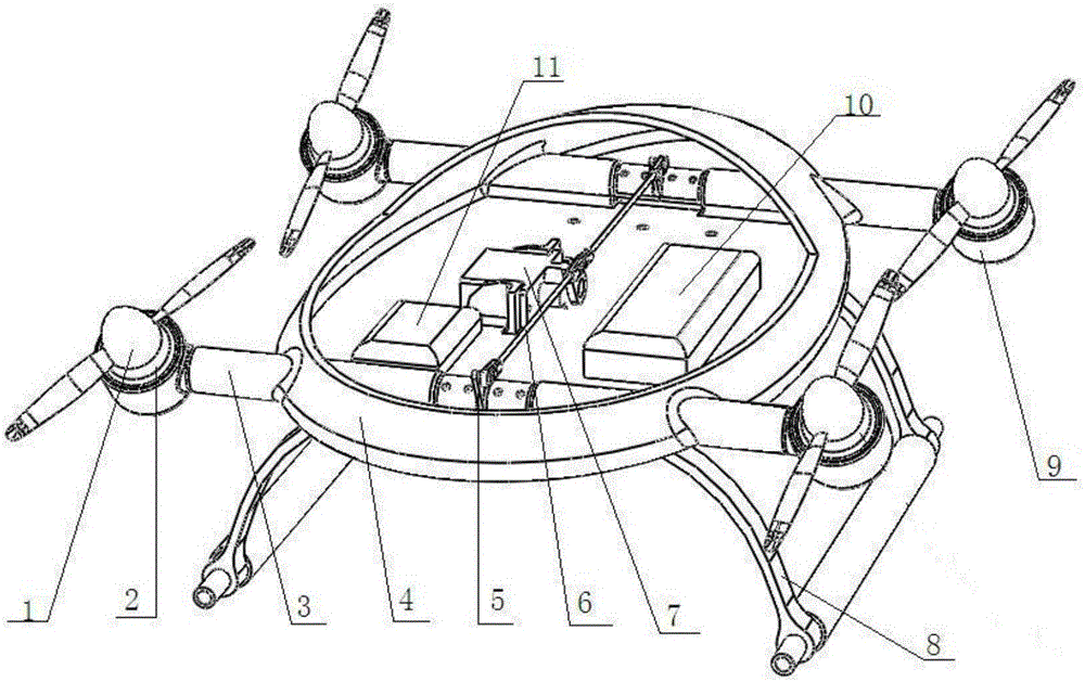
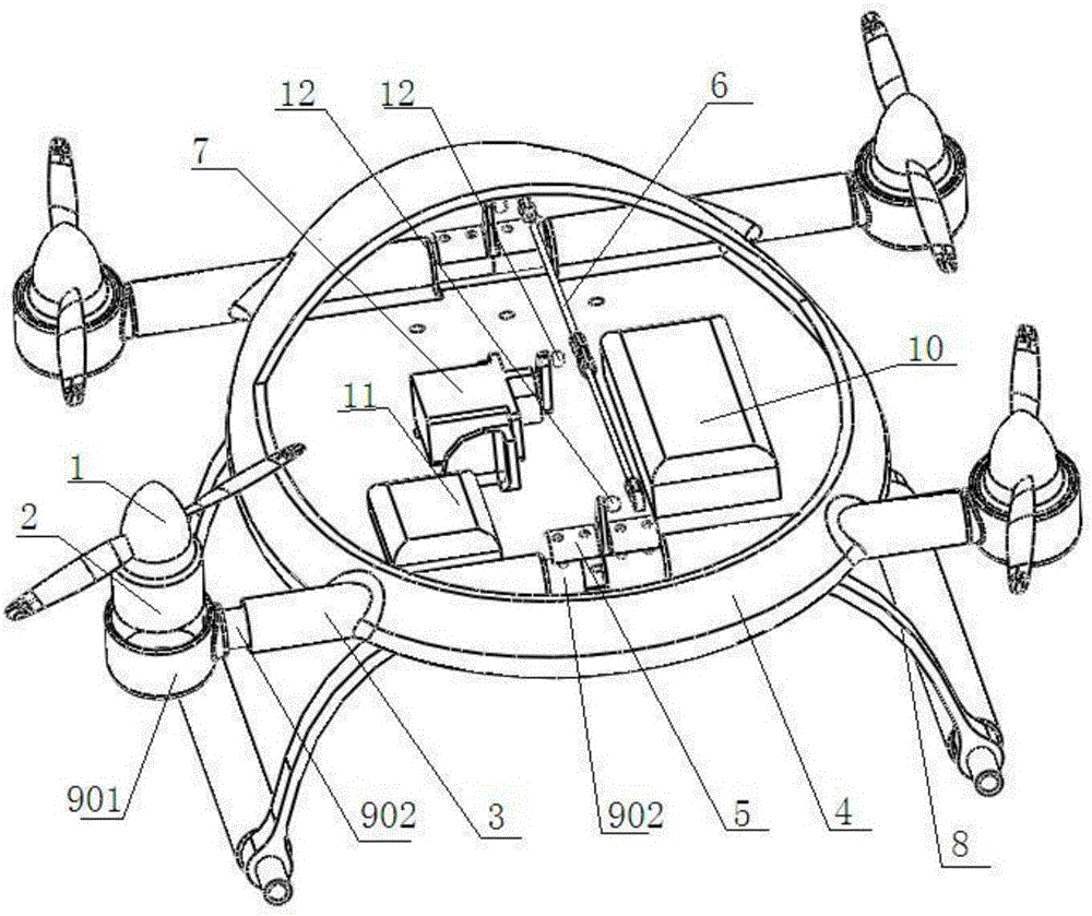
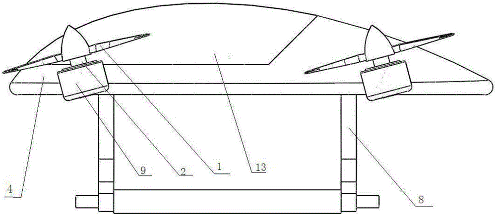
[0029] The invention provides a tilting quad-rotor aircraft, such as Figure 1 ~ Figure 3 As shown, it includes the flying rotor 1, the brushless DC motor 2, the fixed pipe 3, the fuselage 4, the tilting rocker arm 5, the connecting rod 6, the tilting steering gear 7, the landing gear 8, the rotor arm 9, and the power supply unit 10. Flight control system 11, ball head 12, cockpit cover 13. The tilting rocker arm 5, the connecting rod 6, and the tilting steering gear 7 constitute a tilting servo unit, and the flying rotor 1 and the brushless DC motor 2 constitute a power unit.

[0030] The fuselage 4, landing gear 8, and rotor arm 9 are all made of carbon fiber materials. The fuselage 4 is provided with fixed pipes 3 at the left front, right front, right rear, and left rear positions for installing and fixing the rotor arm 9; The tube 3 is glued to the fuselage...


PUM


Abstract

The invention provides a rotated quadrotor, and belongs to the technical field of aircraft design. The rotated quadrotor comprises flying rotor wings, brushless direct current motors, a fuselage, a canopy, undercarriages, a power supply unit, a flight control system, fixing tubes, a rotated rocker arm, a connecting rod, a rotated steering engine, rotor wing arms, and round heads. According to the rotated quadrotor, rotating angles of the four flying rotor wings in the front-back direction are controlled to as to realize forward flying or backward flying; installation angles of the flying rotor wings are changed so as to realize forward flying of the four flying rotor wings, maintain level condition of the fuselage, ensure that the best aerodynamic performance of the quadrotor is maintained all the time, and the maximum lifting force of the fuselage is induced, increase flying speed of the quadrotor, prolong flight duration, and improve wind resistance, operation capability, and efficiency.

Description

Technical field [0001] The invention belongs to the technical field of aircraft design, and in particular relates to a tilting quad-rotor aircraft. Background technique [0002] Quadrotor is an aircraft with four rotor shafts that can take off and land vertically. The motor on each shaft rotates to drive the rotor to generate lift and thrust. The four rotors are evenly distributed around the body, and are configured in pairs. Various flight actions are realized by changing the rotation speed between different rotors. [0003] Due to its simple structure, stable flight, easy operation, and convenient portability, multi-rotor aircraft, especially quadrotor aircraft, have been widely used in various fields at home and abroad in recent years. Compared with traditional helicopters, it has many advantages: its total rotor pitch is fixed and its structure is simple. The blades of each rotor are relatively short, and the linear speed at the end of the blades is slow, the impact force i...

Claims


Application Information

Patent Timeline
11 Nov 2015
Publication
CN105035313A
IPC
B64C27/08; B64C27/52; B64C1/00; B64C27/12
Inventors
王松; 陈万里