A kind of target drone flight control system and flight control method

A flight control system and flight control technology, applied in the field of flight control of aircraft, can solve problems such as the inability to accurately control the timing of leading-edge flaps and trailing-edge flap swings

Active Publication Date: 2017-01-04
BEIJING AEROSPACE KEYI TECH CO LTD +1
View PDF2 Cites 0 Cited by
  • Summary
  • Abstract
  • Description
  • Claims
  • Application Information

AI Technical Summary

Problems solved by technology

However, most of the leading edge flaps and trailing edge flaps disclosed in the prior art are retracted or put down or swing manually, and are also controlled according to the deflection angle of the high-lift device, but these flight control systems cannot accurately control the front flaps. The timing of the swinging of the edge flaps and trailing edge flaps, and how many angles of swinging can make the target aircraft change from the state of the stall angle of attack to the flight state of the high angle of attack

Method used


Image

  • A kind of target drone flight control system and flight control method
  • A kind of target drone flight control system and flight control method
  • A kind of target drone flight control system and flight control method

Examples


Embodiment 1

[0045] Embodiment 1 A kind of target aircraft flight control system

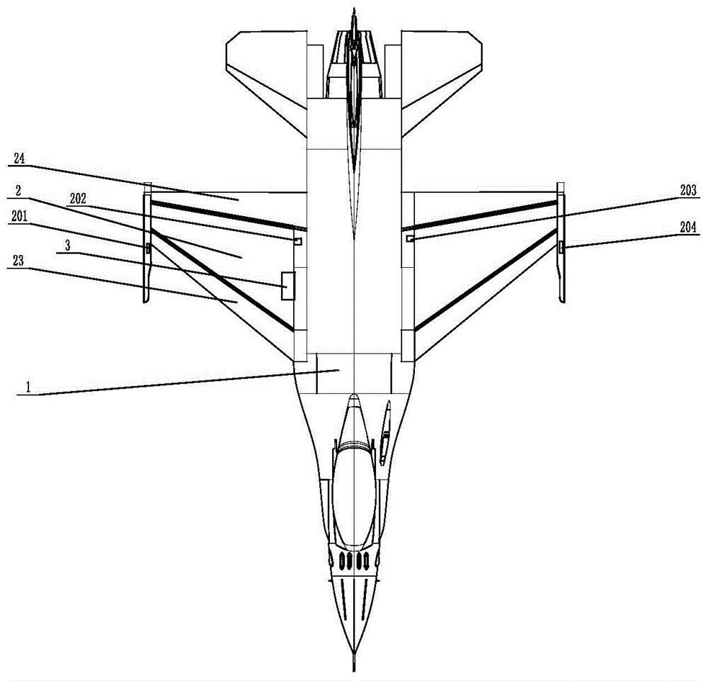
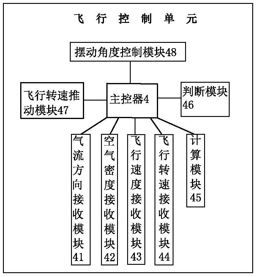
[0046] A target aircraft flight control system, such as Figure 1-2 The flight control system shown includes a flight execution unit, a sensor unit and a flight control unit, wherein,

[0047] The flight execution unit includes a fuselage 1, wings 2 symmetrically arranged on both sides of the fuselage 1 and a thrust vectoring engine 3 arranged in the wings 2; the leading edge and the trailing edge of each wing 2 are respectively arranged There are leading edge flap grooves 23 and trailing edge flap grooves 24, and the leading edge flaps 21 and trailing edge flaps 22 with the same structure are respectively provided in the leading edge flap grooves 23 and the trailing edge flap grooves; The leading edge flap 21 and the trailing edge flap 22 can swing relative to the wing 2, and the swing angles are the same;

[0048] The sensor unit includes an airflow direction sensor 201, a flight speed sensor 202, an air...

Embodiment 2

[0050] Embodiment 2 A target aircraft flight control system

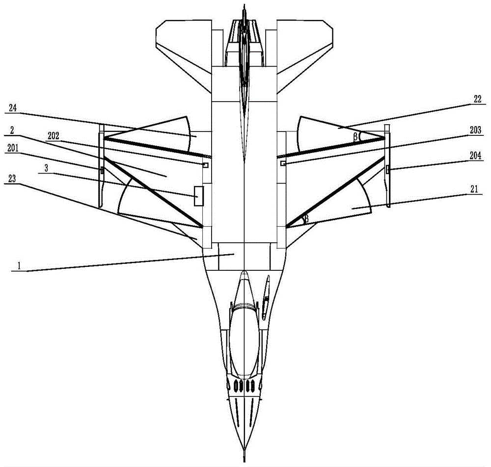
[0051] A kind of target aircraft flight control system, this flight control system is different from embodiment 1, as image 3 As shown; one end of the leading edge flap 21 is hinged in the leading edge flap slot 23 through a first rotating shaft; the corresponding end of the trailing edge flap 22 is hinged through a second rotating shaft into the trailing edge flap groove 24 (not shown in the figure); Protruding inside, the protruding parts are fan-shaped structures with the same area, and the two fan-shaped structures are centrally symmetrical.

Embodiment 3

[0052] Embodiment 3 A target aircraft flight control system

[0053] A target aircraft flight control system, the flight control system is different from Embodiment 1 in that the upper surface of the wing 2 is an arc-shaped upward arch, and the lower surface is an arc-shaped concave upward surface; The upper surface of the wing 2 is pasted with an inflatable layer having the same radius of curvature, and the upper part of the inflatable layer is provided with honeycomb-shaped bumps; The first streamline groove and the second streamline groove that wing 2 trailing edge and leading edge extend; Described first streamline groove and the second streamline groove are respectively provided with first opening and closing valve and second opening and closing valve (figure not shown in); the thrust vectoring engine 3 is provided with two axisymmetric vectoring nozzles, and each axisymmetrical vectoring nozzle includes a steering adjustment actuator, a throat area adjustment actuator, a...


PUM


Abstract

The invention provides a drone aircraft flight control system and method. The drone aircraft flight control system comprises a flight execution unit, a sensor unit and a flight control unit. By means of the relation existing among the wing area, the drone aircraft lift force and the flight rotating speed, the swing angle of a leading edge flap and a leading edge flap is controlled strictly, so that power consumption of an aircraft engine is reduced while enough drone aircraft lift force is ensured.

Description

technical field [0001] The invention belongs to the field of flight control of aircraft, in particular to a flight control system and a flight control method for a target aircraft. Background technique [0002] The flight control system of the target aircraft is a typical nonlinear, strongly coupled, and multivariable system. The slight changes of each variable will have an impact on the flight attitude, flight direction, flight altitude, flight lift and power of the target aircraft. How to make the target aircraft Maintaining a high-lift and high-stability flight state is an urgent technical problem in the field of target drones; most target drones are equipped with high-lift devices on the wings, which mainly include leading edge flaps and trailing edge flaps; The operation method of the high-lift device of the target aircraft is all manually operated by the pilot to control the swing of the leading edge flap and the trailing edge flap. The workload is heavy. Once the tar...

Claims


Application Information

Patent Timeline
Patent Type & Authority Patents(China)
IPC IPC(8): G05D1/08B64D31/06G05D1/10
Inventor 王有闯宋玉成修宏明王国龙朱平廖华龙
Owner BEIJING AEROSPACE KEYI TECH CO LTD
Why Eureka
Try Eureka