
Light bidirectional stacking carrier

A stacker, light technology, applied in the direction of the lifting device, etc., can solve the problems that affect the service life of the forklift, the safety of the forklift, the large current of the controller, and the low efficiency, so as to improve the economy and usability, reduce the model and power, The effect of improving work efficiency

Active Publication Date: 2015-11-11
NOBLEELEVATOR INTELLIGENT EQUIP CO LTD +1
View PDF11 Cites 12 Cited by
  • Summary
  • Abstract
  • Description
  • Claims
  • Application Information

AI Technical Summary

Problems solved by technology

In actual use, the stacking position of goods is often on the side of the vehicle body. Forklifts with this structure need to turn, but due to the small space, such turning is very inconvenient
There are also manufacturers trying side stacking trucks, that is, the movement trajectory of the fork body in the horizontal direction is perpendicular to the central axis of the vehicle body and the forward direction of the vehicle body. Cargo must be turned around, the efficiency is not high, and the space requirement is high
[0004] In order to improve space efficiency, two-way and three-way stacker trucks have also appeared on the market. This kind of forklift can enter the forks on both sides of the car body, but the fork body will make the center of gravity of the whole forklift truck when it carries high-weight goods. Deviating from the central axis, the stability is poor, which affects the service life of the forklift and the safety of the forklift when it is working. In order to improve the stability, the manufacturer will adopt two methods. One is to use the forklift structure announced by the patent document such as the announcement number CN104310279A, including the forearm and lifting rings to help increase lateral stability, but the effect is not good, and the space requirement is high
like Figure 8 as shown, Figure 8 It is a forklift structure in the prior art. The driving wheel and front wheel of the forklift are on the same side of the fork body, and the front wheel of the vehicle is located on the rear side of the cargo, that is, between the center of gravity of the cargo and the driving wheel, which affects the forward stability of the vehicle. Affect the service life of the stacker and the safety of the stacker when it is working
[0005] Another common solution is to increase the weight of the forklift itself and use the weight of the forklift to balance the weight of the goods. However, for this purpose, the self-weight of the forklift must be set very large. Generally, a forklift with eight forklifts is required to lift a ton of goods. With a dead weight of ten tons, the resulting motor power, battery capacity, and controller current are all very large, which greatly wastes energy utilization efficiency
The cost is also very high

Method used


Image

  • Light bidirectional stacking carrier
  • Light bidirectional stacking carrier
  • Light bidirectional stacking carrier

Examples


Embodiment 1

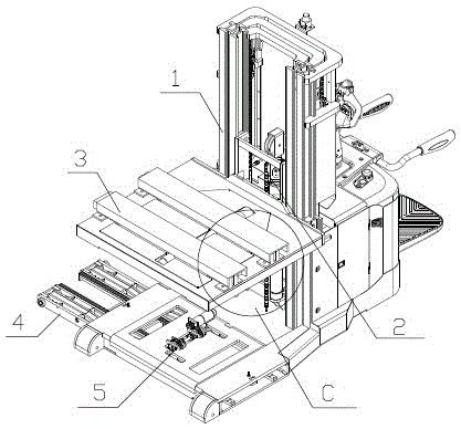
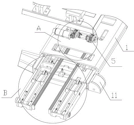
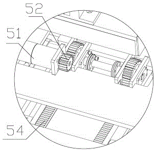
[0045] Example 1, such as figure 1 , figure 2 , image 3 , Figure 4 and Figure 5 Shown: a lateral forklift, including a car body 1, a fork body 3 installed on the car body 1 and a lifting device 2 for lifting the fork body 3 on the car body 1, and the fork body 3 moves laterally; The lateral forklift also includes a load-bearing device 4 for stabilizing the center of gravity of the vehicle body 1 when the fork body 3 picks up objects laterally on the vehicle body 1 and a drive device 5 for driving the load-bearing device 4 to move.

[0046] The vehicle body 1 is provided with a cockpit, and the user sits in the cockpit to drive the vehicle body. The lifting device 2 connects the vehicle body 1 and the fork body 3. Various solutions in the known technology can be used, such as the combination of chains and gears or hydraulic pressure. Lifting rod, adjust the lifting device 2 after the fork body 3 fixes the goods, so that the fork body 3 and the goods are raised, which i...

Embodiment 2

[0053] Embodiment 2: The difference from Embodiment 1 is the difference of the driving device 5. The driver is an oil cylinder and a piston rod. The oil cylinder body is arranged on the car body 1, and the piston rod is connected with the load-bearing device 4 to push the load-bearing device 4 to move on the guide rail. .

Embodiment 3

[0054] Embodiment 3: The difference from Embodiment 1 is the difference of the stabilizing device 7, which includes a telescopic support rod, one end of which is connected to the inner connecting plate 42, and the other end is connected to the outer guide plate 41. The inner connecting plate 42 and the outer guide plate 41 can be at the same height when the load-bearing device 4 is not in working condition, and the load-bearing wheels 43 have a certain height from the ground and do not conflict with the ground; , the inner connecting plate 42 descends, the load-bearing wheels 43 collide with the ground, and the support rod locks its own length immediately, thereby resisting the load-bearing wheels 43, preventing the load-bearing wheels 43 from resetting after being pressed.


PUM


Abstract

The invention relates to the field of mechanical equipment, in particular to a light bidirectional stacking carrier. The technical purpose of the stacking carrier is achieved through the following technical scheme. The light bidirectional stacking carrier comprises a carrier body, a fork body installed on the carrier body and a lifting device used for enabling the forking body to ascend and descend on the carrier body, and the fork body can move laterally in two directions. Front wheels and a drive wheel of the light bidirectional stacking carrier are arranged on the two sides of the fork body in the horizontal face. The light bidirectional stacking carrier further comprises a loading bearing device and a drive device, the load bearing device is used for stabilizing the gravity center of the carrier body when the fork body forks articles on the side of the carrier body, and the drive device is used for driving the load bearing device to move. According to the light bidirectional stacking carrier, the fork body can laterally extend and move in two directions, lateral supporting stability is good, the structure is simple, the dead load of the carrier body is reduced, economical efficiency is good, and popularization is facilitated.

Description

technical field [0001] The invention relates to the field of mechanical equipment, in particular to a light-duty two-way stacker. Background technique [0002] Forklifts are common equipment in the field of logistics. They are suitable for the disassembly, stacking and transportation of goods, and are widely used in workshops, docks, warehouses and other places. [0003] Common forklifts, such as the forklift structure announced by the Chinese patent document CN1495125A, include a forklift body and a fork body. The fork body is often arranged directly in front of the cockpit. The moving directions of the bodies are all parallel. In actual use, the stacking position of goods is often located on the side of the vehicle body. Forklifts with this structure need to turn, but due to the small space, such turning is very inconvenient. There are also manufacturers trying side stacking trucks, that is, the movement trajectory of the fork body in the horizontal direction is perpendi...

Claims


Application Information

Patent Timeline
Patent Type & Authority Applications(China)
IPC IPC(8): B66F9/06
CPCB66F9/14B66F9/06B66F9/146
Inventor 方勇彭飞宇周学军周新英
Owner NOBLEELEVATOR INTELLIGENT EQUIP CO LTD
Learn More