Multilevel rotational flow combined type air atomized fuel nozzle device and control method thereof

An air atomization and fuel nozzle technology, which is used in fuel injection devices, charging systems, engine components, etc., can solve the problems of few main combustion stage swirlers, weak functions, and single swirl organization, etc., to avoid The effect of local oil-rich area, reducing the average equivalence ratio, and avoiding smoke

Active Publication Date: 2015-11-11
INST OF ENGINEERING THERMOPHYSICS - CHINESE ACAD OF SCI
View PDF7 Cites 19 Cited by
  • Summary
  • Abstract
  • Description
  • Claims
  • Application Information

AI Technical Summary

Problems solved by technology

These patents propose a combustor head structure and an oil-gas mixing scheme that can meet the design requirements of a low-pollution combustor with a relatively low air intake in the head and a relatively low oil-air ratio. In the high-temperature rising combustion chamber, the number of main combustion stage swirlers is small, and the swirl flow structure is relatively simple, so it is difficult to achieve efficient and rapid oil-gas mixing at the head of the combustion chamber
[0004] In some patents applied by GE, the strong swirl flow design of the main combustion stage and the weak swirl flow design of the duty stage are adopted, so that the return flow in the combustion chamber is dominated by the main combustion stage. The air of the peripheral main combustion stage with more air volume has a weaker effect on the fuel-rich central duty stage, which makes the duty stage oil and gas mix unevenly, which is not conducive to the improvement of the temperature distribution of the combustion chamber outlet

Method used


Image

  • Multilevel rotational flow combined type air atomized fuel nozzle device and control method thereof
  • Multilevel rotational flow combined type air atomized fuel nozzle device and control method thereof
  • Multilevel rotational flow combined type air atomized fuel nozzle device and control method thereof

Examples


Embodiment Construction

[0039] In order to make the object, technical solution and advantages of the present invention clearer, the present invention will be further described in detail below with reference to the accompanying drawings and examples.

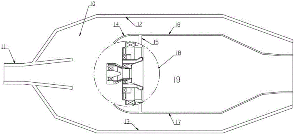
[0040] figure 1 It is a schematic diagram of a combustion chamber 10 with high temperature and increased oil-gas ratio. The combustion chamber is a straight-line single-ring cavity structure. , Outer flame tube 16, inner flame tube 17 and head swirler 18. The high-pressure air is decelerated and diffused by the diffuser 11 and divided into three routes. The first route of air passes through the head swirler 18 and mixes with the fuel, and then enters the combustion zone 19 to participate in combustion. The second and third routes of air flow through the outer casing 12 respectively. The two annular cavities between the outer flame tube 16 and the inner casing 13 and the inner flame tube 17 enter the cooling holes (not shown in the figure) provided on t...


PUM


Abstract

The invention relates to a multilevel rotational flow combined type air atomized fuel nozzle device and a control method thereof. The device is applied to a high temperature rise combustor. A head swirler comprises a central duty level unit and a peripheral primary combustion level unit, a two-level axial swirler structure is adopted by the central duty level unit, an oil membrane generated by duty level fuel oil is atomized under the shearing action of the rotational air of the inner level and the outer level of the duty level, an oil-rich diffusive combustion mode is formed in the duty level, and the problem that the combustion is unstable under small power due to the fact that the gas quantity is large in the head portion of the high temperature rise combustor is avoided; the primary combustion level is of a combined type swirler structure of two-level reverse rotation of weak swirl design, primary combustion fuel oil is sprayed toward the downstream of an axial swirler blade channel of the outer level of the primary combustion level through multiple fuel oil spraying holes, after being atomized and mixed by the rotational air of the inner level and the outer level, the fuel gas in a primary combustion level premix channel is distributed uniformly, and the problem of exhaust smoke at a combustor outlet under the high power of the high temperature rise combustor is avoided.

Description

technical field [0001] The invention is applicable to a combustion chamber of an aero-engine with high temperature and high fuel-air ratio, and relates to a multi-stage swirl combined air atomization fuel nozzle device. Background technique [0002] The thrust-to-weight ratio of military aeroengines is getting higher and higher, which requires continuous improvement of the temperature rise of the combustion chamber. The high temperature rise corresponds to a high oil-gas ratio. In a high-oil-gas ratio environment, if the conventional swirl cup type oil-gas mixing scheme is adopted, the amount of air actually participating in the head combustion is small due to the intake air from the main combustion hole and the mixing hole. The head equivalence ratio will be far more than 1, and there will be serious smoke in the combustion chamber under high power. However, invisible smoke from the exhaust of aero-engines is a requirement for environmental protection, and it is also a tac...

Claims


Application Information

Patent Timeline
Patent Type & Authority Applications(China)
IPC IPC(8): F02M61/18
Inventor 陈浩杨金虎刘存喜刘富强阮昌龙穆勇徐纲
Owner INST OF ENGINEERING THERMOPHYSICS - CHINESE ACAD OF SCI
Why Eureka
Try Eureka