Damping ring device used for controlling vibration of compressor blades

A technology for damping rings and compressors, applied in the field of damping rings, to achieve the effects of small additional mass, high reliability, and simple design

Active Publication Date: 2015-11-11
SHANGHAI JIAO TONG UNIV
View PDF4 Cites 6 Cited by
  • Summary
  • Abstract
  • Description
  • Claims
  • Application Information

AI Technical Summary

Problems solved by technology

[0003] Usually there are two ways to solve the vibration problem. One is to adjust the excitation frequency and the mass and stiffness distribution of the structure by changing the structural parameters, such as geometric shape, size and material, so as to avoid resonance. There are certain limitations in terms of structure

Method used


Image

  • Damping ring device used for controlling vibration of compressor blades
  • Damping ring device used for controlling vibration of compressor blades
  • Damping ring device used for controlling vibration of compressor blades

Examples


Embodiment 1

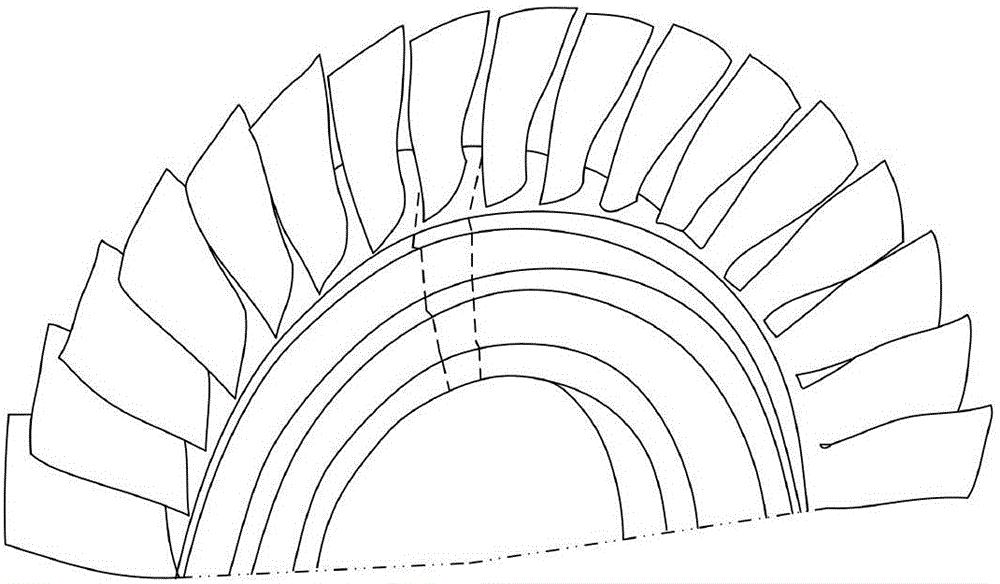
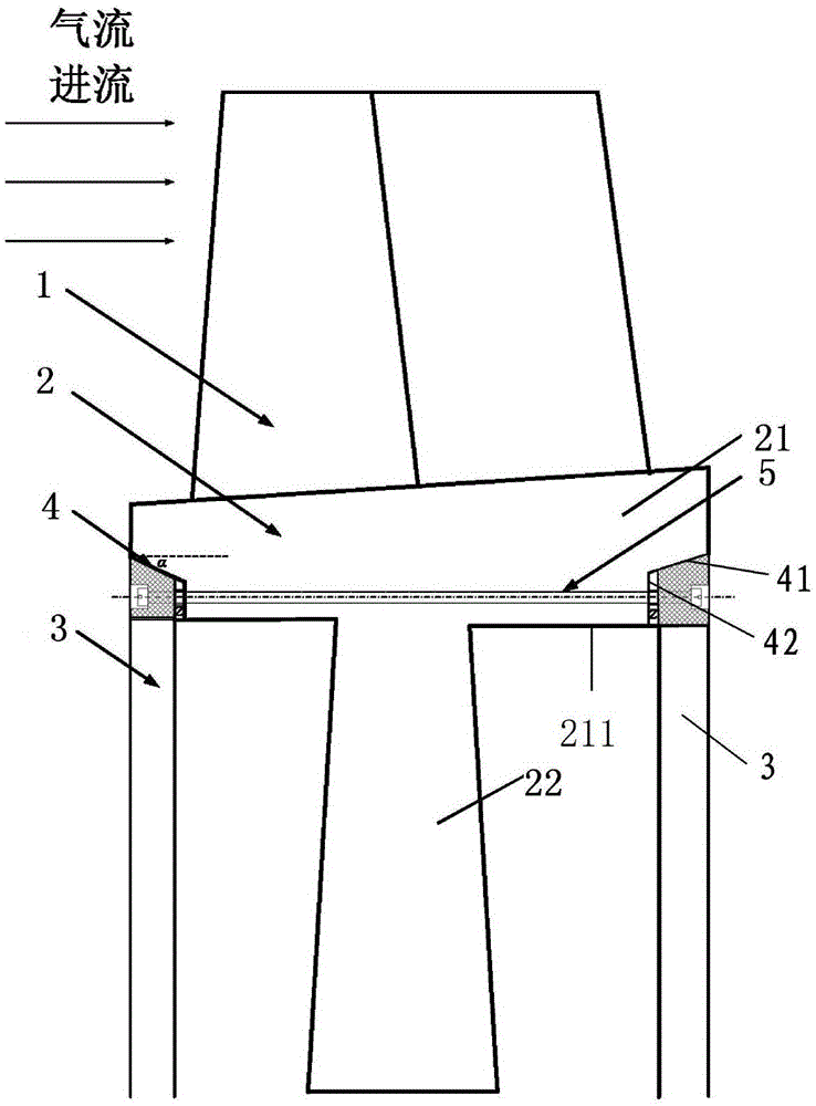
[0043] see figure 1 with 2 , with figure 1 A schematic diagram of the local structure of the compressor blisk of the present invention is disclosed, with figure 2 It is a structural schematic diagram of a single blade in the blisk connected to the damping ring by bolts. A damping ring device for controlling the vibration of compressor blades is provided, including a blade 1, a rim 2 and a damping ring 3, wherein the blade 1 is integrally formed with the rim 2 and is arranged on the rim 2 The outer side of the rim 2 includes a first structure part 21 and a second structure part 22, the second structure part 22 is arranged on the inner side of the first structure part 21, and the first structure part 21 has two A 7-shaped groove 4, the groove 4 is located on the inner side of the end surface of the upstream end of the first structure part 21 and the inner side of the end surface of the downstream end of the first structure part 21; The slot 4 is installed inside the first s...

Embodiment 2

[0052] see Figure 5 The difference between the second embodiment and the first embodiment is that the angle between the first groove surface 41 and the second groove surface 42 is a right angle. That is, when the contact surface between the damping ring 3 and the rim 2 is rectangular, no bolts are needed for connection, and the top of the damping ring 3 and the first groove surface 41 are interference fit, so that The damping ring 3 is locked in the first groove surface 41 .

[0053] During the process of the damping ring 3 being stuck on the first groove surface 41, the size of the damping ring 3 is reduced by using the principle of thermal expansion and contraction, and then it is stuck into the first groove surface 41, and the temperature is restored. When it reaches a normal value, the damping ring 3 and the first groove surface 41 of the rim 2 will be in an overstate due to thermal stress.

[0054] The present invention makes use of the pressure effect of the positioni...


PUM


Abstract

The invention provides a damping ring device used for controlling vibration of compressor blades. The damping ring device comprises the blades, a rim and damping rings. The blades and the rim are integrally formed. The blades are arranged on the outer side of the rim. The rim comprises a first structural part and a second structural part. The second structural part is arranged inside the first structural part. The first structural part comprises two grooves shaped like the Arabic number '7'. The grooves are located in the inner side of the end face of the upstream end of the first structural part and the inner side of the end face of the downstream end of the first structural part. The two damping rings are arranged on the inner sides of the first structural part by being embedded in the grooves respectively. The damping ring device does not make direct contact with the blades. The blades do not need to be machined. Only the procedure of machining wedge-shaped faces or rectangular faces in the rim is needed. The damping ring device is convenient to install and has the advantages of being simple in process, convenient to install, small in added mass, simple in design and high in reliability.

Description

technical field [0001] The invention relates to the technical field of damping rings, in particular to a damping ring device for controlling the vibration of compressor blades. Background technique [0002] The blade is an important component of an aero-engine, and the working environment is harsh, especially the turbine blade, which must withstand high temperature, high pressure, and high speed gas erosion, provide powerful power for the compressor, etc., and bear the impact of periodic changes in the gas nozzle when rotating. During the development and use of the engine, blade vibration failures often occur. According to statistics, blade vibration faults account for about one-third of engine structural faults. In the new machine development stage, this kind of failure is not uncommon. Therefore, it is of great theoretical significance and engineering application value to study the blade, especially the vibration reduction design technology of the turbine blade and its v...

Claims


Application Information

Patent Timeline
Patent Type & Authority Applications(China)
IPC IPC(8): F04D29/66
Inventor 黄修长华宏星
Owner SHANGHAI JIAO TONG UNIV
Why Eureka
Try Eureka