Waterway control valve structure
A technology for waterway control valves and spools, applied in valve details, diaphragm valves, valve devices, etc., can solve the problems of unsuitable solenoid valves, poor applicability, and easy damage of valve diaphragms, so as to avoid water hammer vibration and structural design Reasonable and long-lasting effect
- Summary
- Abstract
- Description
- Claims
- Application Information
AI Technical Summary
Problems solved by technology
Method used
Image
Examples
Embodiment Construction
[0035] In order to further explain the technical solution of the present invention, the present invention will be described in detail below through specific examples.
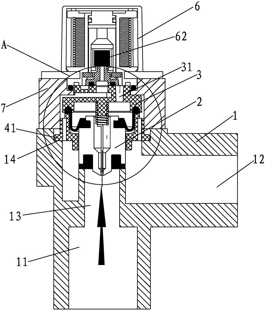
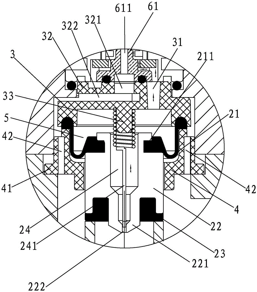
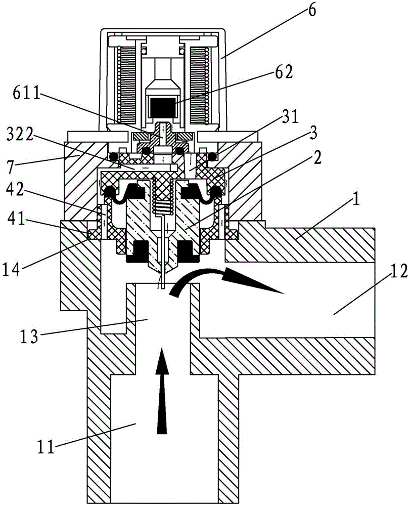
[0036] A waterway control valve structure, such as Figure 1-Figure 2 As shown, it includes a valve body 1 with a water inlet 11 and a water outlet 12, a valve core set 2 installed in the valve body 1, a diaphragm gland 3 and a shaft sleeve 4, and a water inlet 11 and a water outlet 12 are formed. There is a through hole 13 , the diaphragm gland 3 is installed above the spool set 2 , and the spool set 2 is arranged above the through hole 13 .
[0037] The spool kit 2 is composed of a rubber diaphragm 21, a spool body 22 and a water-stop rubber pad 23 from top to bottom. The spool body 22 is provided with a water inlet channel 24, and the lower part of the spool body 22 has a convex post 221. A balance hole 222 is defined at the lower end of the boss 221 , one end of the balance hole 222 communicates with the w...
PUM
 Abstract
Description
Claims
Application Information
 - R&D
- Intellectual Property
- Life Sciences
- Materials
- Tech Scout
- Unparalleled Data Quality
- Higher Quality Content
- 60% Fewer Hallucinations
Browse by: Latest US Patents, China's latest patents, Technical Efficacy Thesaurus, Application Domain, Technology Topic, Popular Technical Reports.
© 2025 PatSnap. All rights reserved.Legal|Privacy policy|Modern Slavery Act Transparency Statement|Sitemap|About US| Contact US: help@patsnap.com


