Cooling structure of flame tube of aero-engine combustor

An aero-engine and cooling structure technology, which is applied in the combustion chamber, continuous combustion chamber, combustion method, etc., can solve the problems of large thermal stress, consumption of cold air, and uneven temperature distribution of the flame tube, and achieves small temperature gradient and cooling air. The effect of small amount and simple structure

Inactive Publication Date: 2015-11-11
NANJING UNIV OF AERONAUTICS & ASTRONAUTICS
View PDF5 Cites 19 Cited by
  • Summary
  • Abstract
  • Description
  • Claims
  • Application Information

AI Technical Summary

Problems solved by technology

In order to further improve the wall cooling effect of the combustion chamber flame tube, researchers at home and abroad have developed a variety of cooling methods, such as full-coverage film cooling, multi-slope hole divergent cooling, floating wall cooling, etc. These cooling tech

Method used


Image

  • Cooling structure of flame tube of aero-engine combustor
  • Cooling structure of flame tube of aero-engine combustor
  • Cooling structure of flame tube of aero-engine combustor

Examples


Embodiment Construction

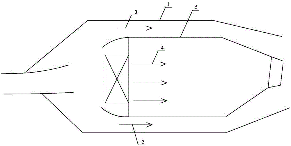
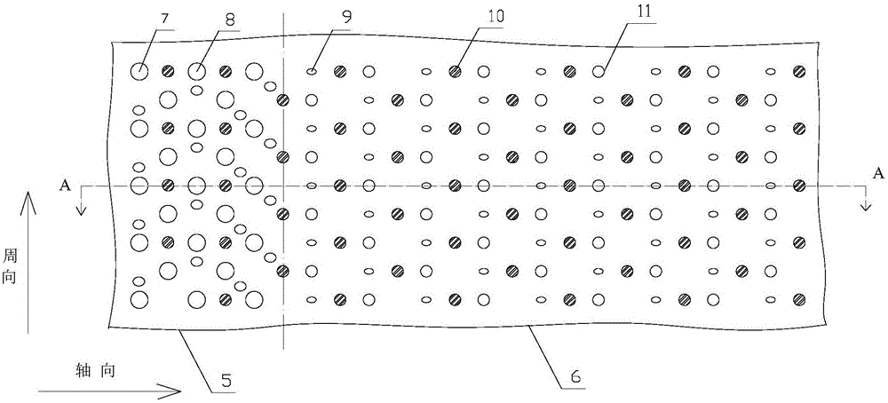
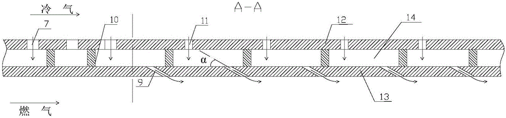
[0031] The present invention will be further explained below in conjunction with the accompanying drawings and specific embodiments. It should be understood that the following specific embodiments are only used to illustrate the present invention but not to limit the scope of the present invention. It should be noted that these drawings are all simplified schematic diagrams, and only schematically illustrate the basic structure of the present invention, so they only show the configurations related to the present invention.

[0032] In describing the present invention, it should be understood that the terms "center", "longitudinal", "transverse", "upper", "lower", "front", "rear", "left", "right", " The orientations or positional relationships indicated by "vertical", "horizontal", "top", "bottom", "inner" and "outer" are based on the orientations or positional relationships shown in the drawings, and are only for the convenience of describing the present invention and Simplif...


PUM

PropertyMeasurementUnit
Apertureaaaaaaaaaa
Apertureaaaaaaaaaa
Diameteraaaaaaaaaa

Abstract

The invention discloses a cooling structure of a flame tube of an aero-engine combustor. The cooling structure comprises a flame tube wallboard. The flame tube wallboard comprises an outer wallboard body and an inner wallboard body. The inner wallboard body is provided with a plurality of diffusion holes, the outer wallboard body is provided with a plurality of impact holes, and all the diffusion holes and impact holes are distributed in a crossing mode. Meanwhile, the inner wallboard body and the outer wallboard body are connected through a plurality of pin fins. The flame tube wallboard is divided into two parts in the axial direction, namely, a front flame tube wallboard segment close to a high-temperature area of the combustor and a rear flame tube wallboard segment far away from the high-temperature area of the combustor. The aperture of the front-segment impact holes in the front flame tube wallboard segment is larger than that of the rear-segment impact holes in the rear flame tube wallboard segment, and meanwhile the aperture of the front-segment diffusion holes in the front flame tube wallboard segment is larger than that of the rear-segment diffusion holes in the rear flame tube wallboard segment. Therefore, a traditional flame tube wall cooling structure is improved, and on the premise of not increasing cold capacity, the cooling potential of the cooling structure is fully tapped, and cooling efficiency is improved. Meanwhile, too large heat stress caused by the excess temperature and uneven temperature distribution of the wall of the flame tube is avoided.

Description

technical field [0001] The invention relates to an aero-engine combustor flame tube, in particular to a cooling structure for the aero-engine combustor flame tube, and belongs to the technical field of aero-engine cooling structure design and thermal protection. Background technique [0002] With the improvement of the thrust-to-weight ratio of aviation gas turbine engines, the design of the combustion chamber is developing towards high temperature rise and high heat capacity. The combustion temperature in the combustion chamber of modern aero-engines is as high as 2000 degrees Celsius and the pressure is as high as 30 atmospheres. As a place for tissue combustion, the flame tube body has been working in a high temperature and high pressure environment for a long time, and it has to bear great thermal stress, creep stress and fatigue stress. One of the key components of reliability. The flame cylinder is generally made of high-temperature resistant alloys, but the current t...

Claims


Application Information

Patent Timeline
IPC IPC(8): F23R3/42
Inventor 谭晓茗单勇张靖周渠立红
Owner NANJING UNIV OF AERONAUTICS & ASTRONAUTICS
Why Eureka
Try Eureka