Check patentability & draft patents in minutes with Patsnap Eureka AI!

Stress measuring system of optical materials

A technology of stress measurement and optical materials, which is applied in the measurement of color/spectral characteristics and the measurement of the change force of optical properties of materials when they are stressed, which can solve the problem of affecting the sensitivity of strain gauges and the inapplicability of glass parts by drilling methods Stress measurement and other issues to achieve accurate and high-precision results

Active Publication Date: 2015-11-11
TSINGHUA UNIV
View PDF7 Cites 9 Cited by
  • Summary
  • Abstract
  • Description
  • Claims
  • Application Information

AI Technical Summary

Problems solved by technology

[0007] 5. Drilling method: As a semi-destructive mechanical measurement method, the drilling method has been widely used in engineering. It has three shortcomings: 1) The residual stress released by drilling decreases sharply with the distance from the hole circumference , there is a certain distance between the strain gauge and the hole circumference, and this distance affects the sensitivity of the strain gauge; 2) The strain gauge only obtains the average value of the released stress within its length range, so it is not suitable for the situation where the residual stress gradient is large; 3 ) drilling method is not suitable for stress measurement of assembled glass parts
[0008] To sum up, although there are many measurement methods for the internal stress of optical materials at home and abroad, some are qualitative or semi-quantitative, some require high-precision standard quarter-wave plates, and some are destructive measurements. For finished samples to be tested, there is an urgent need for a non-destructive, high-precision, simple and easy measurement method

Method used


Image

  • Stress measuring system of optical materials
  • Stress measuring system of optical materials
  • Stress measuring system of optical materials

Examples


Embodiment Construction

[0019] The present invention will be described in detail below in conjunction with the accompanying drawings. However, it should be understood that the accompanying drawings are provided only for better understanding of the present invention, and they should not be construed as limiting the present invention. In the description of the present invention, it should be understood that the terms "first", "second" and so on are only used for the purpose of description, and should not be understood as indicating or implying relative importance.

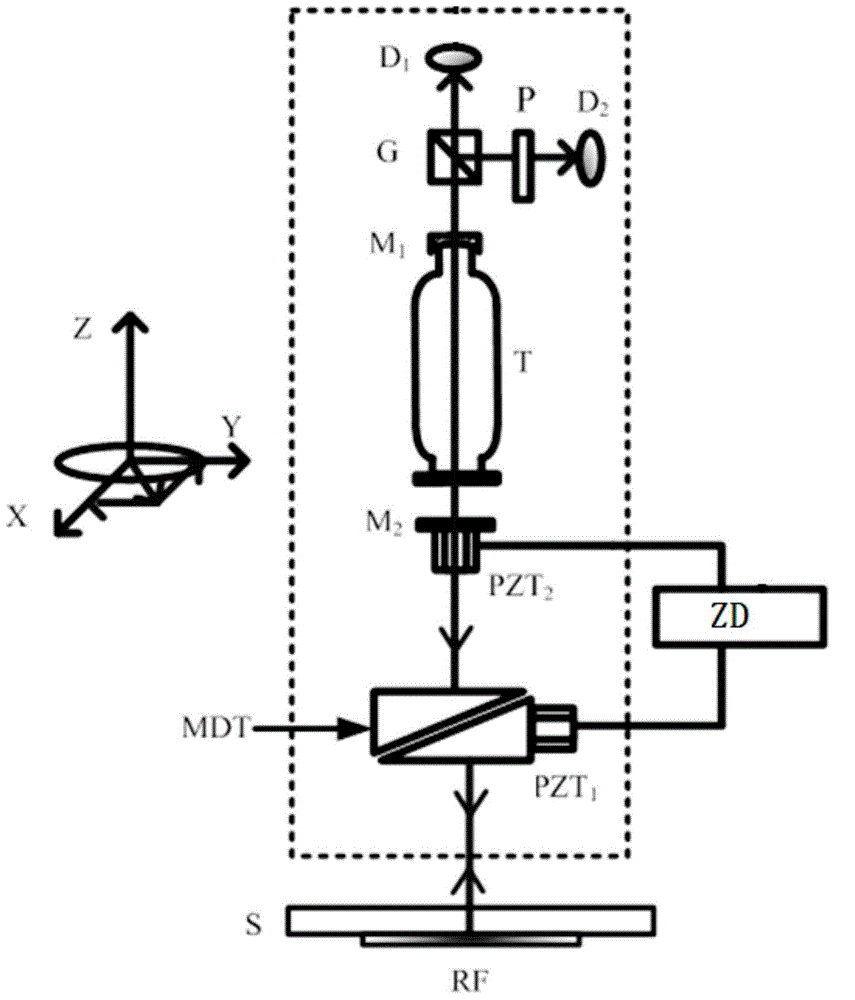
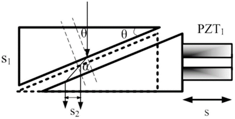
[0020] Such as figure 1 As shown, the present invention provides a kind of optical material stress measurement system, and this stress measurement system comprises a laser T, a beam splitting prism G, a polarizer P, a first photodetector D 1 , a second photodetector D 2 and an external cavity length tuning component MDT, wherein the external cavity length tuning component MDT includes a first glass wedge P 1 , the second glass wedge P 2...


PUM

PropertyMeasurementUnit
Wavelengthaaaaaaaaaa
Wedge angleaaaaaaaaaa

Abstract

The invention relates to a stress measuring system of optical materials. The system comprises a beam splitter prism, a polaroid, a first photoelectric detector, a second photoelectric detector and an external cavity length tuning component. A half-external cavity laser is adopted as a laser. Laser emitted from a first cavity mirror of the laser is vertically incident upon the beam splitter prism. The beam splitter prism divides the output laser into two parts. The two parts of laser are respectively detected and received by the first photoelectric detector and the second photoelectric detector, and a front receiving end of the second photoelectric detector is provided with the polaroid with its light pass direction being vertical to linear polarization direction of the laser output from the laser. Laser emitted from a second cavity mirror of the laser successively passes through a first glass optical wedge and a second glass optical wedge to be emitted onto an optical material sample to be detected. Laser which is reflected by a reflective film at the bottom of the optical material sample to be detected returns along the incipient optical path to the laser so as to modulate the output laser. The stress measuring system provided by the invention can be widely applied in stress measurement of large-area optical glass materials and assembled glass materials.

Description

technical field [0001] The invention relates to a stress measurement system, in particular to an optical material stress measurement system. Background technique [0002] During the processing of optical materials, especially glass, the stress inside the material is always one of the main concerns of people. The existence of different directions and different sizes of stress makes the refractive index of the material different for light with different polarization directions, and stress birefringence occurs, which seriously affects the quality of this optical material. Therefore, the measurement of the internal stress of the material is very important. At present, there are many high-precision stress measurement methods at home and abroad, and the typical stress measurement methods are as follows: [0003] 1. Polarization interferometer: This method is widely used in qualitative or semi-quantitative determination of stress in glass. It usually consists of a white light so...

Claims


Application Information

Patent Timeline
IPC IPC(8): G01L1/24G01N21/39
Inventor 谈宜东牛海莎张书练李继扬
Owner TSINGHUA UNIV
Features
  • R&D
  • Intellectual Property
  • Life Sciences
  • Materials
  • Tech Scout
  • Unparalleled Data Quality
  • Higher Quality Content
  • 60% Fewer Hallucinations
Learn More