
Six-free-degree displacement measurement method of exposure zone on wafer stage

A technology for measuring exposure area and displacement, which is applied in the direction of measuring devices, microlithography exposure equipment, and photolithography exposure devices, etc., which can solve problems such as low calculation accuracy, inability to measure six-degree-of-freedom displacement of the exposure area, and complex algorithms. Achieve the effect of improving measurement accuracy and reducing measurement complexity

Active Publication Date: 2015-11-11
TSINGHUA UNIV +1
View PDF4 Cites 14 Cited by
  • Summary
  • Abstract
  • Description
  • Claims
  • Application Information

AI Technical Summary

Problems solved by technology

The existing technology can realize an integrated reading head to measure the six degrees of freedom of the moving table, but the reading head of the existing planar grating measurement system is mostly placed on the moving table. During the movement of the silicon wafer table, the measurement is fixed on the moving table. The displacement of the point cannot measure the six degrees of freedom displacement of the constantly changing exposure area
In addition, there is a measurement method that measures the displacement of other positions of the moving platform and considers the flexible mode of the moving platform, and calculates it in real time on the exposure area, but this method has low calculation accuracy and complex algorithms

Method used


Image

  • Six-free-degree displacement measurement method of exposure zone on wafer stage
  • Six-free-degree displacement measurement method of exposure zone on wafer stage
  • Six-free-degree displacement measurement method of exposure zone on wafer stage

Examples


Embodiment Construction

[0017] The embodiments of the present invention will be further described in detail below in conjunction with the accompanying drawings.

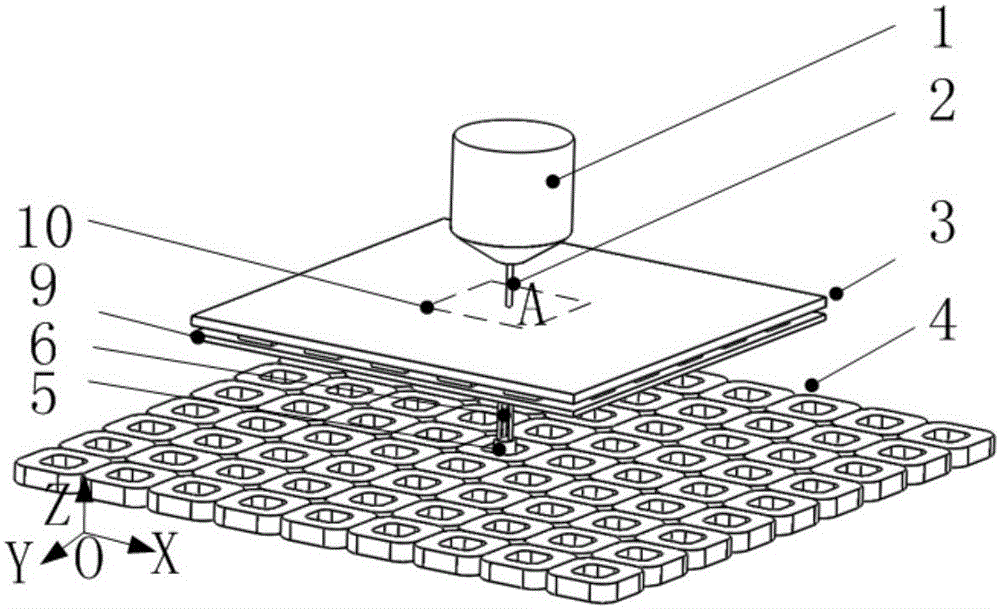
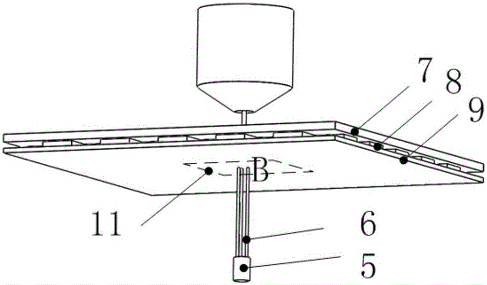
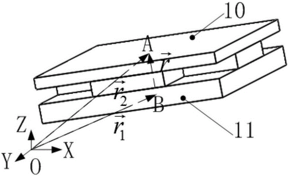
[0018] figure 1 It is a schematic diagram of an embodiment of a six-degree-of-freedom displacement measurement method in the exposure area of ​​a silicon wafer stage provided by the present invention. The silicon wafer stage includes a coil array 4 and a moving stage 3. The coil array 4 is composed of coils arranged in a plane. In this embodiment, square coil. figure 2 It is a schematic diagram of the measurement device in the embodiment. The moving table 3 includes a magnetic steel array 8 and a back plate 7. The magnetic steel array 8 is bonded under the back plate 7. The magnetic steel array 8 adopts a two-dimensional permanent magnet array. In this embodiment A two-dimensional halbach permanent magnet array is used. A planar grating 9 is fixed below the magnetic steel array 8, the measuring surface faces the coil array 4, and the rea...


PUM


Abstract

A six-free-degree displacement measurement method of an exposure zone on a wafer stage is applied in six-free-degree displacement measurement of the exposure zone on the wafer stage. The wafer stage comprises a coil array and a movement bench. A planar optical grating is fixed below a magnetic steel array of the movement bench, so that a reading head is fixed in the gap of the coil array, wherein a central line of the reading head is coincided with a central line of a lens. A measurement zone is formed by an incident measurement light beam from the reading head on the planar optical grating, wherein the centers of the measurement zone and the exposure zone are positioned at the same vertical line. One part, which is covered by the exposure zone, of the movement bench is approximately considered as a rigid body, when the movement bench is deformed due to movement or vibration, the six-free-degree displacement of the exposure zone is obtained by means of calculation of the six-free-degree displacement, which is measured by the reading head, of the measurement zone, thereby achieving six-free-degree displacement measurement of the exposure zone at any time during movement of the wafer stage. The method can reduce measurement complexity and increase measurement precision, and especially can accurately measure the six-free-degree displacement of the exposure zone at any time even the movement bench his high in flexibility.

Description

technical field [0001] The invention relates to a six-degree-of-freedom displacement measurement method for an exposure area of ​​a silicon wafer stage. The six-degree-of-freedom displacement measurement method for the exposure area of ​​a silicon wafer stage is applied to a semiconductor photolithography machine and belongs to the technical field of semiconductor manufacturing equipment. Background technique [0002] During the exposure process of the lithography machine, the silicon wafer is divided into multiple fields of view, which are exposed separately. During the exposure process of a field of view on the silicon wafer, the exposure image is projected onto the silicon wafer through a lens to form an exposure area. In order to ensure exposure accuracy, the wafer stage needs to be leveled, focused, and horizontally adjusted to ensure the relative position and angle between the exposure area and the lens, so the six-degree-of-freedom displacement measurement of the expo...

Claims


Application Information

Patent Timeline
Patent Type & Authority Applications(China)
IPC IPC(8): G03F7/20G01B11/02
CPCG01B11/272G01B11/002G03F7/70775G01D5/38G03F7/70758G01B11/14G03F9/7046
Inventor 朱煜张鸣陈安林成荣杨开明刘峰宋玉晶支凡胡金春徐登峰穆海华胡楚雄
Owner TSINGHUA UNIV
Learn More