
Totally-enclosed calibratable magnetic ring impedance measurement clamp and magnetic ring impedance measurement method

An impedance measurement, fully enclosed technology, applied in the direction of measuring electrical variables, measuring devices, measuring device casings, etc., can solve problems such as difficulty in ensuring the consistency of coil connections, affecting the consistency and stability of measurement results, etc.

Pending Publication Date: 2021-05-14
NORTHWEST INST OF NUCLEAR TECH
View PDF0 Cites 0 Cited by
  • Summary
  • Abstract
  • Description
  • Claims
  • Application Information

AI Technical Summary

Problems solved by technology

However, in order to obtain more accurate complex permeability measurement results below 400MHz, this measurement method still requires separate measurement and compensation of stray parameters
At the same time, since the inductance measurement method does not have a special fixed connection device, it is necessary to rewind or connect the coil on the magnetic ring every time it is measured, and it is difficult to ensure the consistency of the coil connection. Large changes in impedance will affect the consistency and stability of the measurement results

Method used

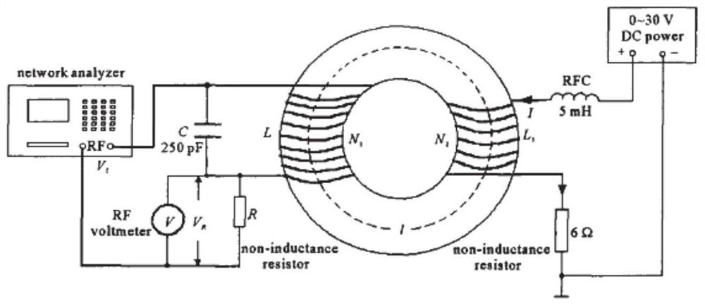

Image

  • Totally-enclosed calibratable magnetic ring impedance measurement clamp and magnetic ring impedance measurement method
  • Totally-enclosed calibratable magnetic ring impedance measurement clamp and magnetic ring impedance measurement method
  • Totally-enclosed calibratable magnetic ring impedance measurement clamp and magnetic ring impedance measurement method

Examples


Embodiment Construction

[0041] Below in conjunction with accompanying drawing, further describe the present invention in detail through embodiment.

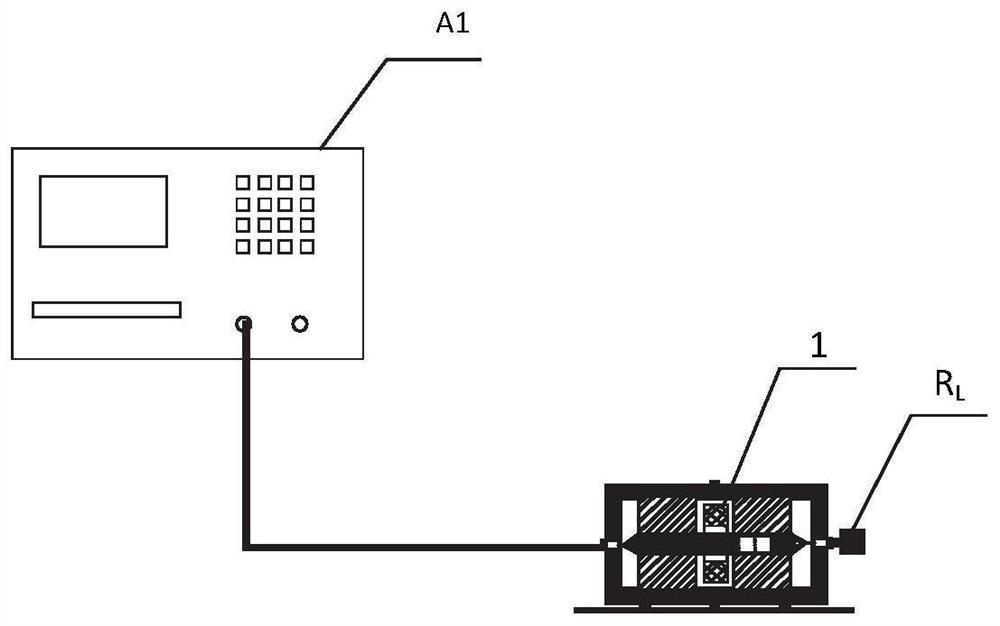
[0042] A test layout for one embodiment of the present invention is as figure 2 Shown, where 1 is the magnetic ring to be tested, A1 is the network analyzer, R L for matching resistors. Before taking measurements, press the figure 2 As shown, connect the network analyzer to one end of the measurement fixture, connect the other end of the fixture to the calibration kit (short circuit, open circuit, and matching), and perform a single-port calibration on the measurement fixture. After the calibration, the other end of the fixture is connected to a matching resistor.

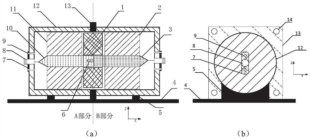
[0043] like image 3 The measuring fixture of an embodiment shown is mainly composed of a metal shell, a cylindrical polytetrafluoroethylene insulating support with a round hole in the middle of the metal shell, a metal coaxial core wire, etc., and the whole is a coaxial structure. The...


PUM


Abstract

The invention provides a totally-enclosed calibratable magnetic ring impedance measurement clamp. The magnetic ring impedance measurement clamp comprises a metal shell, and insulating support pieces and a metal coaxial core wire which are positioned in the metal shell, and the whole clamp is of a coaxial structure; the metal shell is divided into a part A shell and a part B shell; the two ends of the metal shell are respectively provided with an electrical connector; the insulating support pieces are correspondingly divided into a first insulating support piece and a second insulating support piece which are respectively and fixedly arranged in the part A shell and the part B shell, and a space for mounting a to-be-tested magnetic ring is reserved at a position close to the butt joint position of the shell; and the metal coaxial core wire penetrates through the first insulating supporting piece and the second insulating supporting piece and is correspondingly connected with the electrical connectors arranged at the two ends of the metal shell. According to the invention, a totally-enclosed coaxial structure is adopted, so that the influence of high-frequency parasitic capacitance and leakage inductance on a measurement result is avoided; and meanwhile, the coaxial structure is stably limited, so that the accuracy and the consistency of the impedance of the magnetic ring during high-frequency measurement can be improved.

Description

technical field [0001] The invention belongs to the technical field of electromagnetic compatibility, and relates to a magnetic ring impedance measurement fixture and a magnetic ring impedance measurement method. Background technique [0002] The continuous wave radiation test method is a low-level test method that can be tested on large and / or fixed installations to understand the response characteristics of the system to electromagnetic field signals. IEC 61000-4-23 introduces the methods, steps and test equipment for continuous wave testing. As a continuous wave radiation test device, the elliptical radiator has a large radiation range and good low-frequency response, and is a continuous wave radiation test device with better performance. [0003] The elliptical radiator achieves impedance loading through the magnetic ring and the resistance wound on the magnetic ring, and obtains an electromagnetic field similar to a plane wave in the working area. The impedance charac...

Claims


Application Information

Patent Timeline
IPC IPC(8): G01R27/02G01R1/04
CPCG01R27/02G01R1/04G01R1/0425
Inventor 陈鹏秦锋石跃武聂鑫程引会吴刚吴伟
Owner NORTHWEST INST OF NUCLEAR TECH
Learn More