Magnetic latching relay with asymmetric magnetic circuit

A magnetic latching relay, asymmetric technology, applied in electromagnetic relays, electromagnetic relay details, relays, etc., can solve the problems of complex magnetic circuit structure of relays, unfavorable miniaturization design, low performance indicators of relays against harsh environments, and achieve structural Symmetrical, simplified design, convenient suction and reaction force matching effect

Inactive Publication Date: 2015-11-11
G & A TECH
View PDF4 Cites 4 Cited by
  • Summary
  • Abstract
  • Description
  • Claims
  • Application Information

AI Technical Summary

Problems solved by technology

[0006] The technical problem to be solved by the present invention is that the traditional coil magnetic circuit structure with the same two resistance values ​​and the same ampere-turn value is adopted. The size of the yoke or the size of the yoke, as well as the addition of a non-magnetic material between the armature and the yoke, lead to the sacrifice of magnetic efficiency, making the relay magnetic circuit structure complex, not conducive to miniaturization design, and the relay’s anti-harsh environment performance index is low. Magnetic Latching Relay with Symmetrical Magnetic Circuit

Method used


Image

  • Magnetic latching relay with asymmetric magnetic circuit
  • Magnetic latching relay with asymmetric magnetic circuit
  • Magnetic latching relay with asymmetric magnetic circuit

Examples


Embodiment Construction

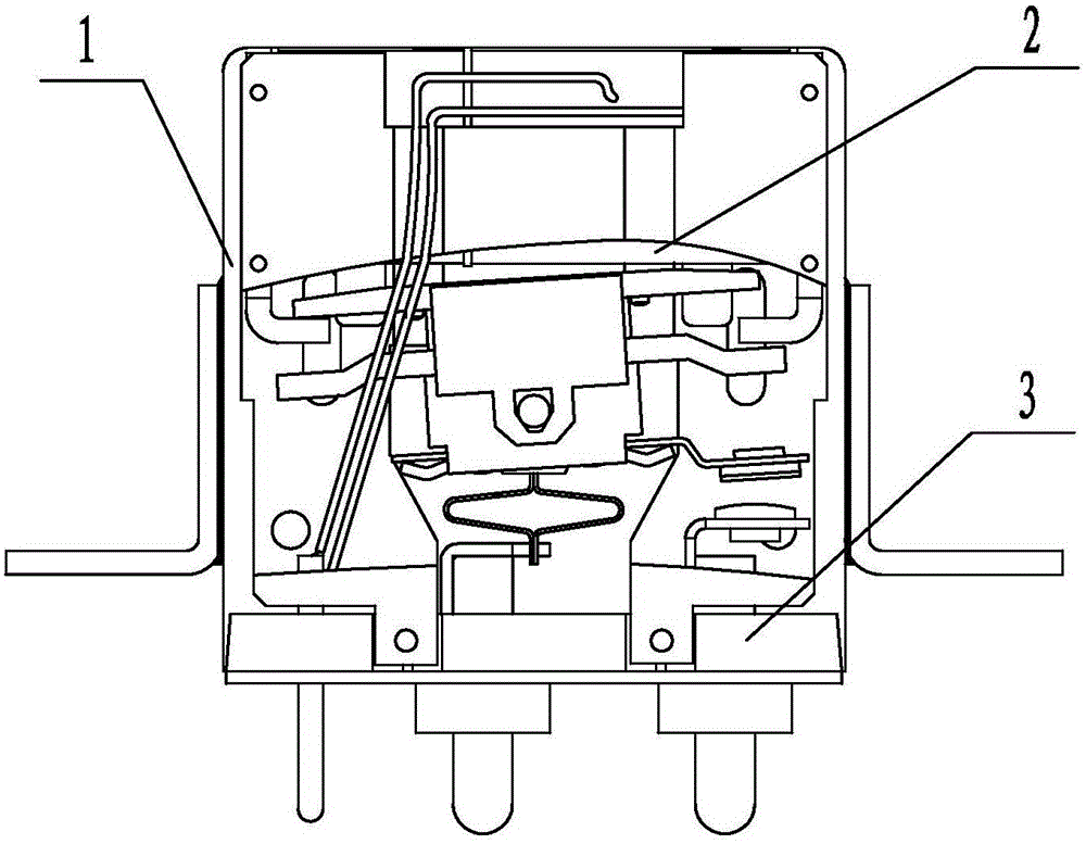
[0027] A magnetic latching relay with an asymmetrical magnetic circuit, such as figure 1 As shown, it is mainly composed of a sealed casing 1, an electromagnetic system 2 and a contact system 3. The electromagnetic system 2 is crimped with the grooves on the base 31 group in the contact system 3 through its two side plates 21 and then connected together by resistance welding to form the whole relay. The entire relay is pressed into the sealed casing 1, and then laser welding is performed on the gap where the two are pressed, so that the entire relay can be welded and sealed to form a magnetic latching relay.

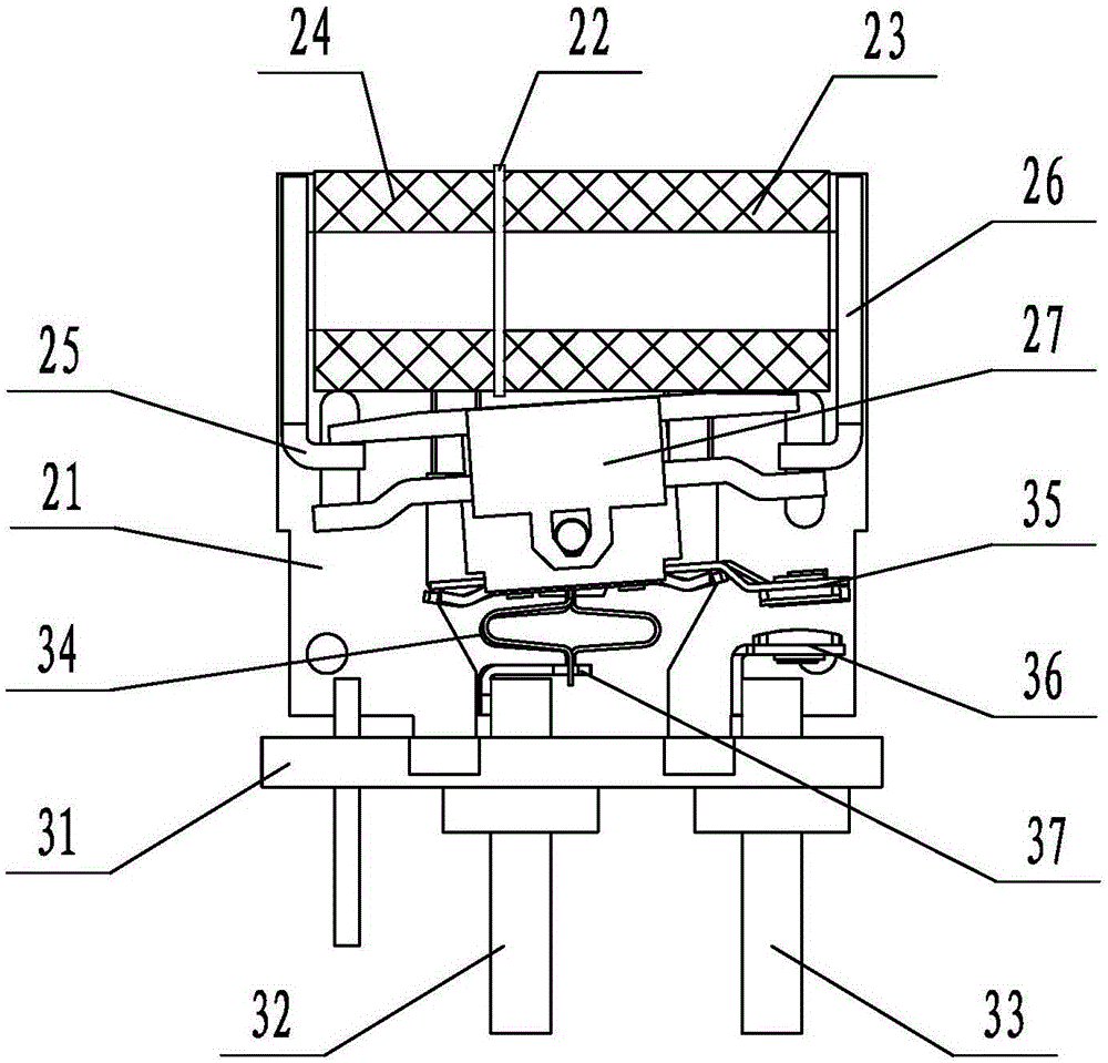
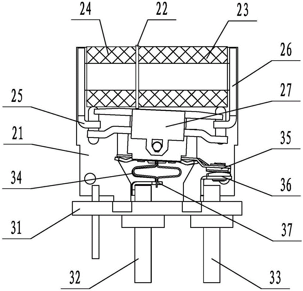
[0028] The electromagnetic system 2 includes a bobbin 22 , a self-holding coil 23 , a return coil 24 , a self-holding yoke 25 , a return yoke 26 and an armature 27 . The coil bobbin 22 is in the shape of a barrel, and is placed horizontally on the upper part of the inner cavity of the sealed casing 1 . The return coil 24 is wound on one side of the outer wall of the bo...


PUM


Abstract

Disclosed in the invention is a magnetic latching relay with an asymmetric magnetic circuit. The magnetic latching relay comprises a sealed housing, an electromagnetic system and a contact system, wherein the electromagnetic system and the contact system are arranged in the sealed housing. The electromagnetic system is arranged above the contact system and has an asymmetric structure; and s corresponding contact of the contact system is in a normally-open state in a return state and a corresponding contact of the contact system is in a normally-closed state in a self-holding state. The contact system consists of a pedestal, an auxiliary contact leading-out rod, a main contact leading-out rod, a connecting spring plate, a movable contact and a static contact; the two ends of the connecting spring plate are respectively connected with an armature and the auxiliary contact leading-out rod; the static contact and the main contact leading-out rod are connected; and the moving contact and the armature are connected. When the armature moves, the moving contact group is driven to move, thereby realizing state conversion. The magnetic latching relay has characteristics of simple magnetic circuit structure, miniaturization design, and high severe environment performance index.

Description

technical field [0001] The invention relates to the field of electromagnetic relay devices, in particular to a magnetic latching relay with an asymmetrical magnetic circuit. Background technique [0002] Magnetic latching relay ML (also known as remanence relay) is a kind of electromagnetic relay and an automatic switch. It generally consists of an electromagnetic system (mainly including coils, permanent magnets, armature components, yoke components, and armature brackets) And contact system (mainly composed of relay base group, static reed, contact, moving contact spring). Like other electromagnetic relays, it plays the role of automatically turning on and off the circuit. Its normally closed or normally open state (or reset state and excitation state) completely depends on the role of permanent magnets, and its switch state is converted by a pulse of a certain width. completed by the signal trigger. When the contact is in the holding state, the coil does not need the re...

Claims


Application Information

Patent Timeline
Patent Type & Authority Applications(China)
IPC IPC(8): H01H50/16H01H50/44H01H50/18H01H50/36
CPCH01H50/16H01H50/18H01H50/36H01H50/44
Inventor 邓力明李明周本胜程贤科
Owner G & A TECH
Why Eureka
Try Eureka