Automatic debugging method for cavity filter

A cavity filter and automatic debugging technology, which is applied to waveguide devices, electrical components, circuits, etc., can solve the problems of high labor costs, time-consuming and laborious, and long education and training cycles, and achieve optimization of the assembly process, simple operation, and debugging. The effect of shortening the time

Active Publication Date: 2015-11-11
深圳市佳信新科技有限公司
View PDF3 Cites 8 Cited by
  • Summary
  • Abstract
  • Description
  • Claims
  • Application Information

AI Technical Summary

Problems solved by technology

[0007] However, the above-mentioned assembly and debugging processes are all carried out manually, which is quite time-consuming and laborious, and the debuggers need to carry out special education and training, the education and training cycle is long, and the labor cost is high, which is the main shortcoming of the prior art

Method used


Image

  • Automatic debugging method for cavity filter
  • Automatic debugging method for cavity filter
  • Automatic debugging method for cavity filter

Examples


Embodiment Construction

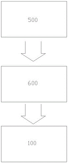
[0034] like Figures 1 to 6 Shown, a kind of automatic debugging method of cavity filter, it comprises the following steps:

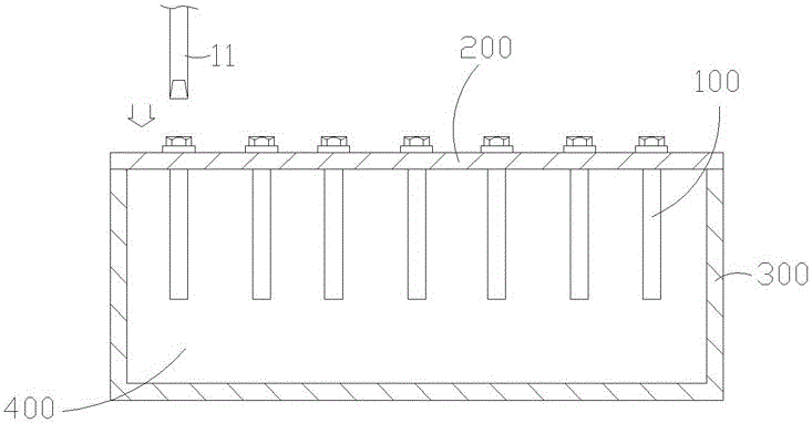
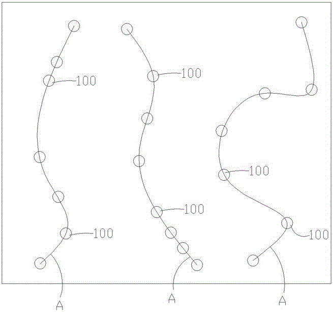
[0035] The first step is to fix several adjusting screws 100 on the cavity filter upper cover 200 , and then install the cavity filter upper cover 200 on the cavity filter box body 300 .

[0036] The cavity filter box 300 has an inner cavity 400 , and a plurality of adjusting screws 100 are extended in the inner cavity 400 to move up and down.

[0037]At this moment, the heights of the portions of the adjustment screws 100 extending in the inner cavity 400 are equal, and the heights enable the bandwidth data of each frequency band to appear.

[0038] The cavity filter changes its inductance and capacitance by changing the height at which the adjustment screw 100 protrudes into the resonant cavity in the cavity 400 .

[0039] During specific implementation, the cavity filter upper cover 200 is mounted on the cavity filter box body 300 using a contour t...


PUM


Abstract

The invention relates to an automatic debugging method for a cavity filter. The method comprises the following steps of the first step: fixing a plurality of adjusting screws on an upper cover of the cavity filter at the same height, and then mounting the upper cover of the cavity filter on a cavity filter casing; the second step: performing prepositioning before automatic debugging, recording X / Y coordinate position information of each adjusting screw, numbering each adjusting screw, and a system controlling an automatic screw driving machine for performing a prepositioning motion of a first adjusting screw within a frequency band before adjustment; the third step: debugging the adjusting screw in the second step; the fourth step: repeating the second step and the third step to complete automatic adjustment of all adjusting screws in the frequency band; and the fifth step: repeating the second step, the third step and the fourth step to complete automatic adjustment of all adjusting screws of all frequency bands of the cavity filter.

Description

technical field [0001] The invention relates to an automatic debugging method for a cavity filter or a combiner, in particular to a method for automatically debugging frequency bands of cavity filters and combiners. Background technique [0002] As we all know, cavity filters and combiners in communication systems are mainly used to combine multi-system signals into an indoor distribution system. For example, in engineering applications, the two frequencies of 800MHZ C network and 900MHz G network are combined and output. Using cavity filter and combiner, a set of indoor distribution system can work in CDMA frequency band and GSM frequency band at the same time. Another example is in the radio antenna system, after the input and output signals of several different frequency bands (such as 145MHZ and 435MHZ) are combined by a combiner, they are connected to the radio station with a feeder line, which not only saves a feeder line, but also avoids The hassle of switching betw...

Claims


Application Information

Patent Timeline
IPC IPC(8): H01P1/207
Inventor 吴府叡施安龙胡东伟谢海成张德朝
Owner 深圳市佳信新科技有限公司
Why Eureka
Try Eureka