Magnetic path structure of outer rotor permanent magnet brushless motor and assembly method of outer rotor permanent magnet brushless motor

A permanent magnet brushless motor and outer rotor technology, applied in the direction of magnetic circuit shape/style/structure, magnetic circuit rotating parts, manufacturing stator/rotor body, etc., can solve the problem of large electrical deviation, affecting control accuracy and system performance, Problems such as mechanical strength and processability are not very good, to achieve the effect of small spacing error, lower requirements, and ensure control accuracy and performance

Inactive Publication Date: 2015-11-11
TIANJIN SANTROLL ELECTRIC AUTOMOBILE TECH CO LTD
View PDF0 Cites 0 Cited by
  • Summary
  • Abstract
  • Description
  • Claims
  • Application Information

AI Technical Summary

Problems solved by technology

[0002] Existing outer rotor permanent magnet brushless motors generally use the motor casing as the mechanical output end, such as electric bicycle hub motors, traction machines, fan motors, and electric actuators. Staggered and pasted on the inner circle of the casing, but due to the limitation of processing technology, the size of the magnetic steel has a certain tolerance range, and there will be a certain gap between two adjacent magnetic steels, because the polarity of the adjacent two magnetic steels is opposite , when installing, two adjacent magnets will be attracted together, and there will be no gap between the end faces, resulting in a relatively large gap between the last magnet and the first magnet, then the last magnet and the first The electrical deviation of a piece of magnetic steel reaches the maximum. For occasions that require high control position accuracy, such as servo, electric execution, etc., it will greatly affect the control accuracy and system performance. This processing technology can no longer meet the use requirements; At the same time, since the casing is used as the rotor yoke, the material of the casing is usually required to be a material with high magnetic permeability such as electrical pure iron, No. 10 steel or No. 20 steel, and the mechanical strength and processability of these materials are not very good. , which is not conducive to the processing of the casing and the output and utilization of motor power

Method used


Image

  • Magnetic path structure of outer rotor permanent magnet brushless motor and assembly method of outer rotor permanent magnet brushless motor
  • Magnetic path structure of outer rotor permanent magnet brushless motor and assembly method of outer rotor permanent magnet brushless motor
  • Magnetic path structure of outer rotor permanent magnet brushless motor and assembly method of outer rotor permanent magnet brushless motor

Examples


Embodiment approach

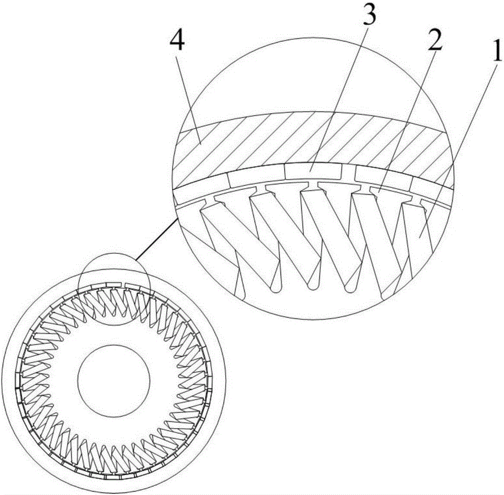
[0028] Such as figure 1 Shown is a schematic diagram of the magnetic circuit structure of the existing outer rotor permanent magnet brushless motor, wherein 1 is the stator winding, 2 is the stator core, 3 is the magnetic steel, and 4 is the casing. The stator core 2 is closely matched with the motor shaft. The entire motor body is supported by the motor shaft. Due to the limitation of the processing technology, the size of each magnet will have a certain tolerance. Since the magnetic poles of the adjacent magnets are opposite, the adjacent magnets will be attracted together during assembly. , which will result in a large distance between the last magnet and the first magnet (such as figure 1 The gap in the middle), and the uneven assembly of the magnetic steel will lead to uneven force on the motor during operation and low control accuracy. For motors that require high control accuracy (such as stepping motors and servo motors that require precise rotation) ), the uneven ass...


PUM


Abstract

The invention discloses a magnetic path structure of an outer rotor permanent magnet brushless motor. The magnetic path structure comprises a stator and a rotor, wherein the stator comprises a stator core, a winding and a shaft, wherein the shaft and the stator core are in tight fit for supporting the stator; the rotor comprises a rotor core, magnetic steel and a machine case; the machine case and the rotor core are in tight fit for mechanical output; the magnetic path structure is characterized in that the rotor core comprises a plurality of symmetrical magnetic steel tanks; and a bump is reserved between two adjacent magnetic steel tanks and is used for positioning the magnetic steel.

Description

technical field [0001] The invention relates to an outer rotor permanent magnet brushless motor, in particular to a magnetic circuit structure and an assembly method of the outer rotor permanent magnet brushless motor. Background technique [0002] Existing outer rotor permanent magnet brushless motors generally use the motor casing as the mechanical output end, such as electric bicycle hub motors, traction machines, fan motors, and electric actuators. Staggered and pasted on the inner circle of the casing, but due to the limitation of processing technology, the size of the magnetic steel has a certain tolerance range, and there will be a certain gap between two adjacent magnetic steels, because the polarity of the adjacent two magnetic steels is opposite , when installing, two adjacent magnets will be attracted together, and there will be no gap between the end faces, resulting in a relatively large gap between the last magnet and the first magnet, then the last magnet and ...

Claims


Application Information

Patent Timeline
Patent Type & Authority Applications(China)
IPC IPC(8): H02K1/27H02K15/03
Inventor 余国权
Owner TIANJIN SANTROLL ELECTRIC AUTOMOBILE TECH CO LTD
Why Eureka
Try Eureka